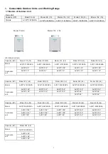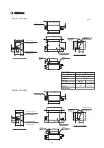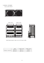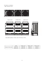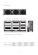
Item
Mark
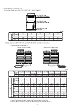
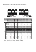
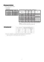
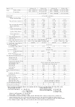
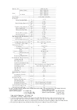
Allowable Piping Length (*13)
< the recommended
connectable number
of Indoor Unit
> the recommended
connectable number
of Indoor Unit
Total Piping Length
Total Liquid Piping
Actual Length
< 1,000m (*14)
< 300m
Maximum Piping Length
Actual Length
L1
< 165m
< 165m
Equivalent Length
< 190m
< 190m
L
< 90m
< 40m
Maximum Piping Length between
Branch pipe of 1st Branch and Each Indoor Unit
Maximum Piping Length between
Each Branch pipe and Each Indoor Unit
L
< 40m
< 30m
Total Piping Length between
Switch Box and Each Indoor Unit
* L4
* a+b+c+d+e
HCH-160D:
< 30m
HCH-160D: < 30m
HCH-80D:
< 10m
HCH-80D:
< 10m
Piping Length between Piping Connection Kit 1 and
Each Outdoor Unit
L5
< 10m
< 10m
Height Difference between
Outdoor Units and Indoor Units
O.U. is Higher
H1
< 50m
< 50m
O.U. is Lower
< 40m
< 40m
Height Difference between Indoor Units
H
< 15m
< 15m
Height Difference between
H
< 4m
< 4m
H4
< 15m
< 15m
Indoor Units using the Same Switch Box
Height Difference between Switch Box
Height Difference between Outdoor Units
H5
< 0.1m
< 0.1m
NOTES:
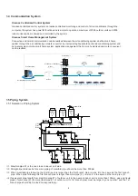
1. Check the gas pipe and liquid pipe are equivalent in terms of the piping length and piping system.
2. Use a branch pipe (system components) for the branch pipe of indoor unit and Switch Box.
3. Install the outdoor unit, branch pipe and Switch Box according to each “Installation & Maintenance Manual”.
4. If the piping length (L3) between each branch pipe and each indoor unit is considerably longer than other indoor unit,
refrigerant may not flow well and also performance may be deteriorated compared to other models
(Recommended Piping Length: within 15m)
(*1): The piping connection kit is counted from the indoor unit side (as Piping Connection Kit 1).
(*2): When the maximum length of the equivalent refrigerant pipe (L1) from the outdoor unit/piping connection kit 1 to the
indoor unit is over 100m, the pipe size of gas/liquid line from the outdoor unit/piping connection kit 1 to first branch
should be increased with the reducer (field-supplied)
(*3): If the refrigerant piping length is more than 100m, no need to increase the pipe size after first branch.
If the branch pipe size is larger than the first branch, adjust the branch pipe size to the first branch. In case that the
selected pipe size after the first branch is larger than the pipe size before the first branch, use the same pipe siz
e
as before the branch.
(*4): The pipe diameter
6
should be the same as the indoor unit piping connection size.
(*5): When the liquid piping length is longer than 15m, use
f
9.53 pipe and reducer (field-supplied)
(*6): Keep the direct distance of 500mm or more after the piping connection kit.
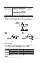
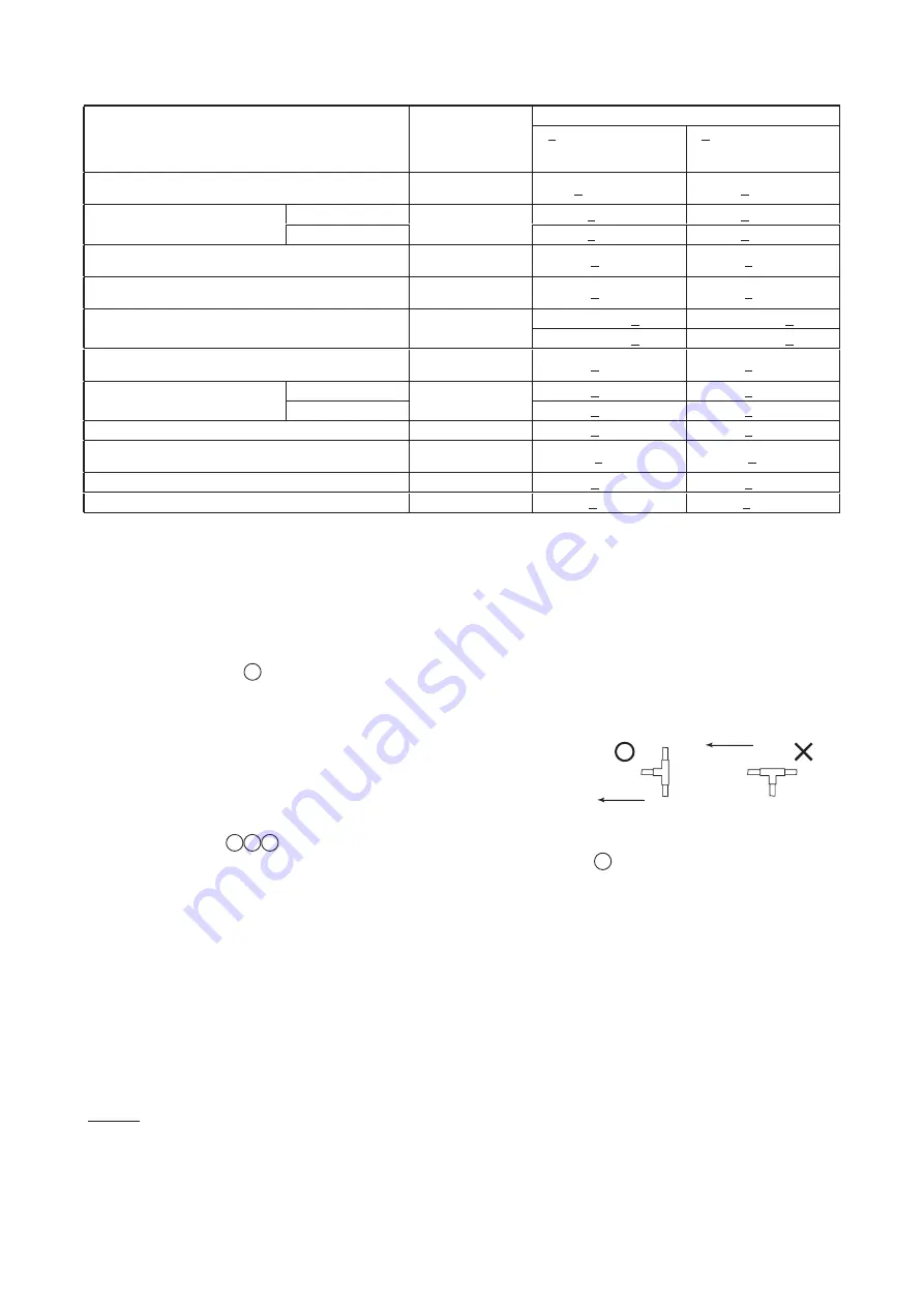
(*7): In case of the line branch, if the length of the pipe between the terminal
branch of 3 pipes (specified in the figure of mark F) and the farthes
indoor unit exceeds 5m, use a T-branch to the applicable liquid pipe of
3 branches. (Corresponding to the Same Diameter as JIS B8607)
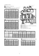
(*8): In case that the number of connectable indoor unit exceeds four, the high/low pressure gas pipe, gas pipe and
liquid pipe (Fig.
4 5 6
) need to increase one size respectively.
(*9): The liquid pipe is not required to connect to the Switch Box. Refer to Table
6
for the liquid pipe diameter between
multi-kit and indoor unit.
(*10): In case that the combination of indoor unit capacity is 96kBtu/h for HCH-280D, the performance may decrease
approximate 5% in cooling and 10% in heating.
(*11): The excess of the total capacity may cause insufficient p rformance and abnormal sound. Be sure to connect
within the allowable total capacity.
(*12): For the exclusive cooling operation, connect indoor units with low pressure gas pipe and liquid pipe (without Switch
Box). The total capacity of the exclusive cooling operation should be smaller than 50% of the total indoor unit
capacity.
(*13): The condition of refrigerant piping installation is different depending on the connected indoor unit quantities.
(*14): Allowable total piping length may become shorter than 1,000m due to the limitation of maximum additional
refrigerant amount.
(*15): In case that a branch is located downstream of the Switch Box and also the connected indoor unit capacity is
7~14kBtu/h use
f
15.88 for the gas pipe.
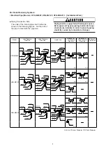
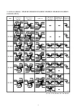
● Piping Work Conditions (Refer to the figure of previous age.)
Upstream
Upstream
Installation of Liquid T-Branch
11

