ϥ
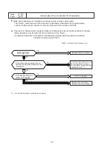
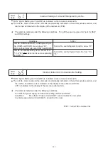
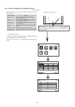
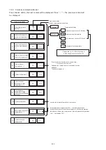
“RUN” light is flashing and “ALARM” are indicated on the remote control switch.
The unit No., alarm code and the unit code are alternately indicated on the set temperature
section, and the unit No. and alarm code are indicated on the outdoor unit PCB1.
★
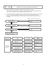
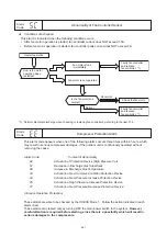
IPM (Transistor Module) has detect
ed
function of abnormality.
This alarm is indicated when the transistor module detects the abnormality seven times in 30 minutes.
(Retry operation is performed up to the occurrence of six times.)
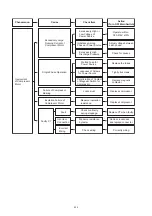
Conditions of Activation:
Abnormal Current to the Transistor Module such as Short Circuited or Grounded
Abnormal Temperature of the Transistor Module
Control Voltage Decrease
Alarm
Code
Inverter Error Signal Detection
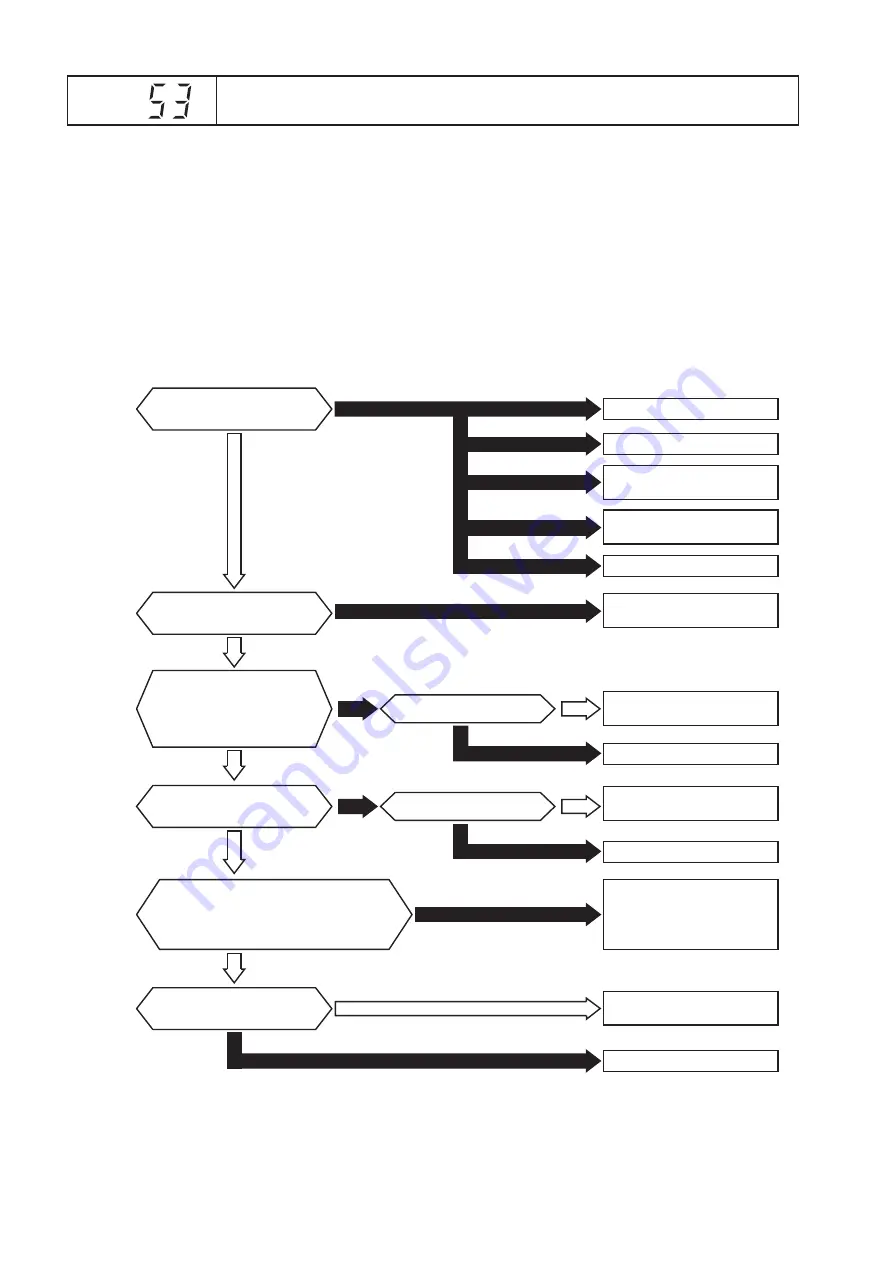
Yes
Yes
Faulty
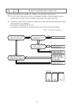
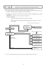
Turn off power, disconnect
U, V, W from compressor
terminals and restart.
Does the protecting function
activate? *3)
Check the transistor
module. *1) *2)
Normal
No
Is the heat exchanger of
outdoor unit clogged?
Replace the PCB2.
Remove clogging or
replace the heat exchanger.
Replace the transistor module.
Check the compressor.
Check the compressor.
Check fan motor.
Yes
Yes
Is the silicon grease coated all over
between the transistor module and the
radiated fin?
Is the fixed screw on the transistor
module loose?
No
No
No
Coat the silicon grease to all
the touched face between
the transistor module and the
radiated fin fully. Fix the
screw correctly.*4)
Check the PCB2.
Check the compressor.
Normal
Normal
Replace the PCB2 and
the transistor module.
Failure of PCB2.
Replace the PCB2.
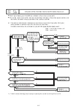
Check pressure and
refrigerant cycle.
Connect power line
to CT (Current Transformer).
Is high pressure increased?
Check clogging for
heat exchanger.
Yes
(It trips immediately.)
No (It trips after a certain period.)
Restart operation.
Does it trip soon?
Is power line is
connected to CT?
Abnormal
Abnormal
(Itc=1, 12)
(Itc=21)
PCB1: Control PCB in Outdoor Unit
PCB2: Inverter PCB
*
*
*
3): Turn ON the No.1 switch of the dip switch DSW1 on PCB2 when restarting with disconnecting the terminals of the
compressor. After troubleshooting, turn OFF the No.1 switch of the dip switch DSW1 on PCB2.
4): Use the silicon grease provided as accessory.
1): Perform electrical discharge when replacing or checking inverter parts by referring to the item 13.
4
.
2): Regarding checking method of transistor module, refer to the item 13.
4
.
*
233

