background image

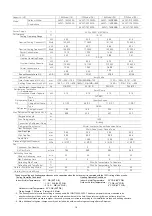
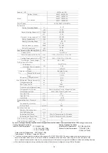
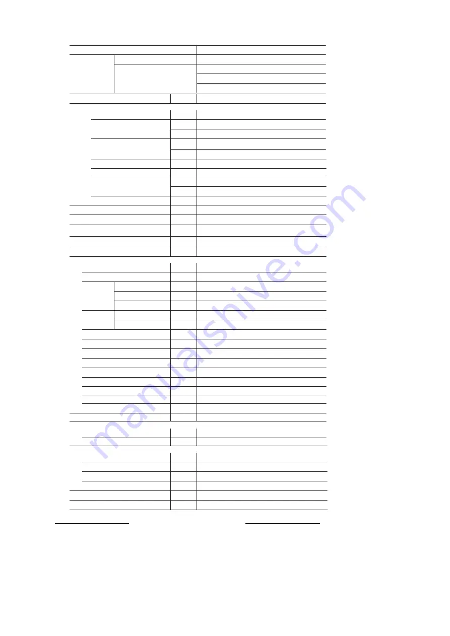
454Model 


AVWT-454

FESZA

AVWT-

154FESSA

AVWT-

154FESSA

AVWT-

154FESSA

ą

_

L8

3.5

#UVI

464

2

L8

140.4

#UVI

479

045

L8

39.48

ą

_

L8

150.0

#UVI

51

1

9

L8

37.50

68

/

63

NN

NN

LH

954

990

L8

'7$%

-

17.1

/

6.6

3"

31.5

LH

86.9

Chargeless Length

N

N


NN

38.1

NN

19.05

.1B

— 

N

NJO

585

NJO

NJO

NN

NN

"$´7

~415V

Hz 

Max.Piping Length

Connections Refrigerant Piping

Refrigerant Flow Control

Capacity

὇)1Ὀ

Model

Outdoor Model

Power Supply


Power Consumption 

Heating Operating Range

Nominal Heating Capacity


Power Consumption 

Cabinet Color

Outer Dimensions (Hx W x D)

Packing Dimensions(H x W x D)

Net Weight(Gross Weight)

Compressor

Crankcase Heater Capacity

Refrigeration

 Oil

Type

Brand

Charge(Unit/Comp.)

Refrigerant

Type

Hole for Power Supply Wiring

Hole for Control Line Wiring

Condenser Fan Quantity

Air Flow Rate

Ivory White

Micro-computer Control Expansion Valve

Multi-Pass Cross-Finned Tube

The above cooling and heating capacities show the capacities when the outdoor unit is operated with the 100% rating of indoor units,

   Cooling Operation Conditions
   Indoor Air Inlet Temperature:

27

 DB (80

o

F DB)

1  19

 WB (66.2

°

F WB)

2  19.5

 WB (66°F WB)

Heating Operation Conditions
Indoor Air Inlet Temperature:    20

o

C DB (68

o

F DB)

Outdoor Air Inlet Temperature:  7

o

C DB (45

o

F DB)

 6

o

C WB (43

o

F WB)

   Outdoor Air Inlet Temperature: 35

o

C DB (95

o

F DB)

   Piping Length:  7.5 Meters,   Piping Lift:  0 Meter

 3:  The sound pressure is tested according to the appendix B of GB/T18836-2002. The above parameters were measured in an 

         anechoic chamber with no echo, so the echo should be considered in the field. When return air grille is on bottom plate of the    

         duct or external static pressure is higher, the sound pressure will increase according to the installation method and building structure.

 4:  Max. additional refrigerant charge quantity has included the outdoor unit refrigerant charge Before Shipment 

Conbination

Performance

Refrigerating Installation

Pressure(High/Low Pressure)

Mininum Defrosting

 time

Max.Defrosting time
Defrosting Start Temp
Defrosting end Temp(Tube)

Fan

Defrosting Condition

Scroll Comp

Idemitsu Kosan

Brazing

With Air Temperature Ta Calculate

With Air Temperature Ta Calculate

Cooling Operating Range

Nominal Cooling Capacit

y

Ą

Nominal Cooling Capacit

y

Ą

Charge Amount

Max Refrigerant Charge Amount

Ą


Heat Exchanger Type

Low 

Gas Pipe

Liquid


Pipe

L

Sound Pressure Level(380/208V/Night-Shift)

3


E# "

17

2

0×(1

210

+

1210+1210

)×750

1

8

82

×(1

278+1278+1278

82

8

NN

31.75

High 

Gas Pipe

18

Summary of Contents for AVWT-114FESSA

Page 1: ...door Units Models AVWT 76 96FESRA AVWT 114 154FESSA Specifications in this catalogue are subject to change without notice in order that Hisense may bring the latest innovations to their customers Add...

Page 2: ...ce of heat exchanger the fin surface repels wate As a result drain water splashes outside of the drain pan and splashed water runs inside of electrical box In the end water leakage or electrical devic...

Page 3: ...ided will result in death or serious injury WARNING indicates a hazardous situation which if not avoided could result in death or serious injury CAUTION used with the safety alert symbol indicates a h...

Page 4: ...s accident Refrigerant leakage can cause difficulty with breathing due to insufficient air Turn OFF the main switch extinguish any naked flames and contact your service contractor if refrigerant leaka...

Page 5: ...e to wear leather gloves to prevent cold injuries Protect the wires electrical parts etc from rats or other small animals If not protected rats may gnaw at unprotected parts and which may lead to a fi...

Page 6: ...r consumption of the device and an activation of switch Therefore check the field regulations and standards before performing electrical work in order to protect the power supply for the packaged air...

Page 7: ...Correction Based On Refrigerant Piping Length 51 4 6 Correction Factor According to Defrosting Operation 53 4 7 Electrical Data 54 4 8 Sound Data 55 5 Component Data 61 6 Control System 65 6 1 Refrige...

Page 8: ...128 12 5 Automatic Simple Judgement System for Refrigerant Amount 129 12 6 Consideration 130 13 Setting of DIP Switches 131 13 1 Function of RSW DSWs and LEDs 131 13 2 Function of RSW DSW LED 133 13...

Page 9: ...AVWT 272FESZA AVWT 290FESZA AVWT 308FESZA AVWT 324FESZA AVWT 340FESZA AVWT 136 AVWT 154 AVWT 154 AVWT 136 AVWT 154 AVWT 136 AVWT 136 AVWT 154 AVWT 96 AVWT 96 Capacity HP Model 364 38 Model 382 40 Mod...

Page 10: ...i Flexi R series indoor units has been extended up to 104 indoor units in 12 types to meet various building requirements Available Indoor Unit Type Nominal Capacity kBtu h 07 09 12 14 17 18 22 24 27 3...

Page 11: ...ANT 1 In a system where all indoor units operate at the same time total of these indoor units should not be larger than combined capacity of the outdoor units or otherwise overload may occur under sev...

Page 12: ...entralized control system can realize centralized monitoring and control of all air conditioners through the computer the system has powerful functions and is simple to operate a maximum of 2048 outdo...

Page 13: ...ssure Gas 19 05 5 4 5 4 8 6 High Pressure Gas 15 88 19 05 Liquid 9 5 9 5 1 7 1 7 1 7 Model Combination Unit Outdoor Unit A Outdoor Unit B Piping Connection Kit HFQ M202F HFQ M212F Piping Size a Low Pr...

Page 14: ...Low Pressure Gas 8 6 8 6 8 6 1 75 1 75 1 75 1 75 High Pressure Gas 5 4 5 4 8 6 8 6 8 6 Liquid 15 88 15 88 15 88 19 05 19 05 19 05 19 05 c Low Pressure Gas 5 4 8 6 8 6 8 6 8 6 8 6 8 6 8 6 High Pressure...

Page 15: ...M452F 170 to 232 HFQ M562F 250 to 340 HFQ M692F 264 to 510 HFQ M902F Pipe Diameter and Branch Pipe after First Branch Total Indoor Unit kBtu h Low Pressure Gas High Pressure Gas Liquid Model fmm fmm f...

Page 16: ...2 7 OD 28 6 ID 19 05 ID 31 75 ID 38 1 ID 38 1 ID 32 0 ID 28 6 31 75 31 75 28 6 ID 31 75 ID 38 1 ID 38 1 ID 32 0 ID 28 6 31 75 31 75 28 6 ID 31 75 ID 38 1 ID 38 1 ID 32 0 ID 28 6 31 75 31 75 28 6 ID 22...

Page 17: ...2 2 22 2 22 2 22 2 22 2 22 2 22 2 22 2 22 2 25 4 22 2 22 2 22 2 22 2 19 05 19 05 19 05 19 05 19 05 19 05 25 4 19 05 12 7 12 7 12 7 9 53 9 53 9 53 9 53 ID9 53 ID9 53 ID9 53 ID6 35 ID6 35 12 7 9 53 9 53...

Page 18: ...154 to 170 8 6 1 7 170 to 50 8 6 15 88 4 Pipe Diameter between Switch Box to Branch pipe 3 Pipes and 2 Pipes 9 Switch Box Model Max Combination of Indoor Unit 8 Available Combination of Indoor Unit C...

Page 19: ...ase the pipe size after first branch If the branch pipe size is larger than the first branch adjust the branch pipe size to the first branch In case that the selected pipe size after the first branch...

Page 20: ...nch pipe First Branch and Each Indoor Unit L2 Main Piping Branch Indoor Unit Capacity Ratio After Main Branch Piping Length After Branch Number of Main Piping Branch 40m a b c 30m or d e f 30m without...

Page 21: ...NJO Max Defrosting time NJO Defrosting Start Temp With Air Temperature Ta Calculate Defrosting end Temp Tube With Air Temperature Ta Calculate Hole for Power Supply Wiring NN Hole for Control Line Wir...

Page 22: ...ure 27 DB 80o F DB 1 19 WB 66 2 F WB 2 19 5 WB 66 F WB Heating Operation Conditions Indoor Air Inlet Temperature 20o C DB 68o F DB Outdoor Air Inlet Temperature 7o C DB 45o F DB 6o C WB 43o F WB Outdo...

Page 23: ...the 100 rating of indoor units Cooling Operation Conditions Indoor Air Inlet Temperature 27 DB 80o F DB 1 19 WB 66 2 F WB 2 19 5 WB 66 F WB Heating Operation Conditions Indoor Air Inlet Temperature 2...

Page 24: ...nsion Valve Multi Pass Cross Finned Tube The above cooling and heating capacities show the capacities when the outdoor unit is operated with the 100 rating of indoor units Cooling Operation Conditions...

Page 25: ...ling Operation Conditions Indoor Air Inlet Temperature 27 DB 80o F DB 1 19 WB 66 2 F WB 2 19 5 WB 66 F WB Heating Operation Conditions Indoor Air Inlet Temperature 20o C DB 68o F DB Outdoor Air Inlet...

Page 26: ...peration Conditions Indoor Air Inlet Temperature 20o C DB 68o F DB Outdoor Air Inlet Temperature 7o C DB 45o F DB 6o C WB 43o F WB Outdoor Air Inlet Temperature 35o C DB 95o F DB Piping Length 7 5 Met...

Page 27: ...erant Piping Connection C Field Supplied Pipe Size Hole for Power Supply Wiring 52 x 2 Hole for Refrigerant Piping and Control Line Wiring Hole for Power Supply Wiring Electrical Control Box Hole for...

Page 28: ...Hole for Power Supply Wiring 52 x 2 Electrical Control Box Hole for Refrigerant Piping and Control Line Wiring 4 Holes 38 x 15 729 18 18 131 948 131 276 50 less than 30 Brazing Concrete Foundation 70...

Page 29: ...el HCH 160D HCH 280D Power Supply Refrigerant AC 1 220 240V 50 60Hz R410A Input W 20 Connectable Indoor Unit Total Capacity less than 54kBtu h 55 to 96kBtu h Number of Connectable Indoor Unit 1 to 7 1...

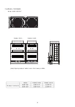
Page 30: ...r Unit A Outdoor Unit B Standard Combination AVWT 170 AVWT 96 AVWT 76 Note Spacing between outdoor units in this drawing is 20mm 282 or more 131 688 18 18 729 131 688 950 950 20 or more 1920 765 Outdo...

Page 31: ...n AVWT 190 AVWT 114 AVWT 76 AVWT 212 AVWT 136 AVWT 76 Two Module Combination Model AVWT 190 212 Note Spacing between outdoor units in this drawing is 20mm 282 or more 131 948 131 688 18 18 729 950 121...

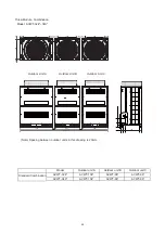
Page 32: ...or Unit B Standard Combination AVWT 232 AVWT 114 AVWT 114 AVWT 250 AVWT 136 AVWT 114 Model AVWT 232 308 AVWT 272 AVWT 136 AVWT 136 AVWT 290 AVWT 154 AVWT 136 AVWT 308 AVWT 154 AVWT 154 765 282 or more...

Page 33: ...or unit A AVWT 136 AVWT 154 Outdoor unit B AVWT 96 AVWT 96 Outdoor unit C AVWT 96 AVWT 96 765 282 or more 131 948 18 18 729 282 or more 688 131 688 1210 20 or more 950 950 20 or more 3150 Note Spacing...

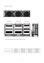
Page 34: ...d Combination AVWT 382 Outdoor unit A AVWT 154 AVWT 154 Outdoor unit B AVWT 114 AVWT 136 Outdoor unit C AVWT 96 AVWT 96 AVWT 398 AVWT 154 AVWT 154 AVWT 96 765 18 18 729 282 or more 131 948 948 282 or...

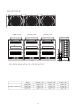
Page 35: ...Combination AVWT 438 Outdoor unit A AVWT 154 AVWT 154 Outdoor unit B AVWT 154 AVWT 154 Outdoor unit C AVWT 114 AVWT 136 AVWT 454 AVWT 154 AVWT 154 AVWT 154 765 18 18 729 282 or more 131 948 948 282 or...

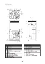
Page 36: ...9 Stop Valve Low Pressure Gas 10 Stop Valve High Pressure Gas 11 Stop Valve Liquid 12 Solenoid Valve 3pcs No Part Name 13 Check Joint Low 14 Check Joint High 15 Check Joint for Oil 16 Electrical Box...

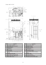
Page 37: ...ersing Valve 2pcs 10 Stop Valve Low Pressure Gas 11 Stop Valve High Pressure Gas 12 Stop Valve Liquid No Part Name 13 Solenoid Valve 3pcs 14 Check Joint Low 15 Check Joint High 16 Check Joint for Oil...

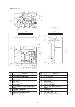
Page 38: ...sing Valve 2pcs 10 Stop Valve Low Pressure Gas 11 Stop Valve High Pressure Gas 12 Stop Valve Liquid No Part Name 13 Solenoid Valve 3pcs 14 Check Joint Low 15 Check Joint High 16 Check Joint for Oil 17...

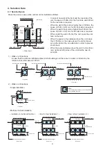
Page 39: ...the air outlet side in order to prevent short circuit When there are obstacles above the unit the four front rear right and left sides of the unit shall be open in principle This indicates the directi...

Page 40: ...e is higher and also the short circuit is likely to occur compared to the installation condition nd an appropriate dimension by calculating air ow current 3 For the multiple installation 1 group allow...

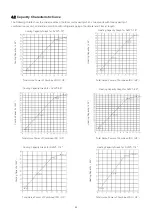
Page 41: ...Horse Power of Combined IDU 1 Total Horse Power of Combined IDU 1 Cooling Capacity Graph for AVWT 96 Heating Capacity Graph for Cooling Capacity L8 Heating Capacity L8 Total Horse Power of Combined ID...

Page 42: ...54 Cooling Capacity Graph for AVWT 170 Total Horse Power of Combined IDU 1 Total Horse Power of Combined IDU 1 Total Horse Power of Combined IDU 1 Total Horse Power of Combined IDU 1 Total Horse Power...

Page 43: ...32 Heating Capacity Graph for AVWT 232 Cooling Capacity L8 Total Horse Power of Combined IDU 1 Cooling Capacity L8 Total Horse Power of Combined IDU 1 Cooling Capacity L8 Total Horse Power of Combined...

Page 44: ...87 Heating Capacity Graph for AVWT 287 Cooling Capacity L8 Total Horse Power of Combined IDU 1 Cooling Capacity L8 Total Horse Power of Combined IDU 1 Cooling Capacity L8 Total Horse Power of Combined...

Page 45: ...40 Heating Capacity Graph for AVWT 340 Cooling Capacity L8 Total Horse Power of Combined IDU 1 Cooling Capacity L8 Total Horse Power of Combined IDU 1 Cooling Capacity L8 Total Horse Power of Combined...

Page 46: ...98 Heating Capacity Graph for AVWT 398 Cooling Capacity L8 Total Horse Power of Combined IDU 1 Cooling Capacity L8 Total Horse Power of Combined IDU 1 Cooling Capacity L8 Total Horse Power of Combined...

Page 47: ...54 Heating Capacity Graph for AVWT 454 Total Horse Power of Combined IDU 1 Total Horse Power of Combined IDU 1 Total Horse Power of Combined IDU 1 Total Horse Power of Combined IDU 1 Total Horse Power...

Page 48: ...ble for AVWT 114 Table 4 Cooling Capacity Table for AVWT 136 Table 5 Cooling Capacity Table for AVWT 154 Capacity Table Under Different Temperature KW Outdoor Air Inlet Dry Bulb Indoor Air Inlet Wet B...

Page 49: ...ng Capacity Table for AVWT 232 Table 10 Cooling Capacity Table for AVWT 250 Outdoor Air Inlet Dry Bulb Indoor Air Inlet Wet Bulb Outdoor Air Inlet Dry Bulb Indoor Air Inlet Wet Bulb Outdoor Air Inlet...

Page 50: ...city Table for AVWT 324 Table 15 Cooling Capacity Table for AVWT 340 Outdoor Air Inlet Out Dry Bulb Indoor Air Inlet Wet Bulb Outdoor Air Inlet Out Dry Bulb Indoor Air Inlet Wet Bulb Outdoor Air Inlet...

Page 51: ...city Table for AVWT 420 Table 20 Cooling Capacity Table for AVWT 438 Outdoor Air Inlet Out Dry Bulb Indoor Air Inlet Wet Bulb Outdoor Air Inlet Out Dry Bulb Indoor Air Inlet Wet Bulb Outdoor Air Inlet...

Page 52: ...s the normal value of cooling operation In some cases the value may change due to the compressor protection control 2 The value on the table shows when the system is operating under the following cond...

Page 53: ...le for AVWT 96 Table 3 Heating Capacity Table for AVWT 114 Table 4 Heating Capacity Table for AVWT 136 Outdoor Air Inlet Web Bulb Indoor Air Inlet Dry Bulb Outdoor Air Inlet Web Bulb Indoor Air Inlet...

Page 54: ...Heating Capacity Table for AVWT 190 Table 8 Heating Capacity Table for AVWT 212 Outdoor Air Inlet Web Bulb Indoor Air Inlet Dry Bulb Outdoor Air Inlet Web Bulb Indoor Air Inlet Dry Bulb Outdoor Air I...

Page 55: ...12 Heating Capacity Table for AVWT 287 Outdoor Air Inlet Web Bulb Indoor Air Inlet Dry Bulb Outdoor Air Inlet Web Bulb Indoor Air Inlet Dry Bulb Outdoor Air Inlet Web Bulb Indoor Air Inlet Dry Bulb Ou...

Page 56: ...Capacity Table for AVWT 340 16 18 20 22 24 20 71 2 71 2 71 0 70 6 70 6 15 81 5 80 8 81 0 80 5 80 0 10 91 0 90 7 90 3 90 0 89 3 5 102 0 101 5 101 2 100 9 100 5 0 109 7 109 5 109 1 108 1 107 2 5 125 5...

Page 57: ...9 Heating Capacity Table for AVWT 420 Table 20 Heating Capacity Table for AVWT 438 Outdoor Air Inlet Web Bulb Indoor Air Inlet Dry Bulb Outdoor Air Inlet Web Bulb Indoor Air Inlet Dry Bulb Outdoor Air...

Page 58: ...the normal value of heating operation In some cases the value may change due to the compressor protection control 2 The value on the table shows when the system is operated under the following conditi...

Page 59: ...for Cooling Capacity According to Piping Length The cooling capacity should be corrected according to the following formula CCA CC F CCA Actual Corrected Cooling Capacity CC Cooling Capacity in the Pe...

Page 60: ...r for Cooling Capacity According to Piping Length The heating capacity should be corrected according to the following formula CCA CC F CCA Actual Corrected Cooling Capacity CC Cooling Capacity in the...

Page 61: ...wfall or a operation in a transitional period The heating capacity in the preceding paragraph excludes the condition of the frost or the defrosting operation period In consideration of the frost or th...

Page 62: ...4 AVWT 382 AVWT 398 AVWT 420 AVWT 438 AVWT 454 Fuse Model Unit Main Power Applicable Voltage Maximum Fuse Current MCA 7_ 577 7_ 577 7_ 577 7_ 577 7_ 577 7_ 577 7_ 577 7_ 577 7_ 577 7_ 577 7_ 577 7_ 57...

Page 63: ...4 8 Sound Data Model AVWT 76 Model AVWT 96 Model AVWT 114 Model AVWT 136 55 Power Supply 380 415V 50Hz Power Supply 380 415V 50Hz Power Supply 380 415V 50Hz Power Supply 380 415V 50Hz...

Page 64: ...Model AVWT 154 Model AVWT 170 Model AVWT 190 Model AVWT 212 56 Power Supply 380 415V 50Hz Power Supply 380 415V 50Hz Power Supply 380 415V 50Hz Power Supply 380 415V 50Hz...

Page 65: ...Model AVWT 232 Model AVWT 250 Model AVWT 272 Model AVWT 290 57 Power Supply 380 415V 50Hz Power Supply 380 415V 50Hz Power Supply 380 415V 50Hz Power Supply 380 415V 50Hz...

Page 66: ...Model AVWT 308 Model AVWT 324 Model AVWT 340 Model AVWT 364 58 Power Supply 380 415V 50Hz Power Supply 380 415V 50Hz Power Supply 380 415V 50Hz Power Supply 380 415V 50Hz...

Page 67: ...Model AVWT 382 Model AVWT 398 Model AVWT 420 Model AVWT 438 59 Power Supply 380 415V 50Hz Power Supply 380 415V 50Hz Power Supply 380 415V 50Hz Power Supply 380 415V 50Hz...

Page 68: ...Model AVWT 454 60 Power Supply 380 415V 50Hz...

Page 69: ...inal blast volume m3 min Quantity Fan Part Fan Type Axial flow Fan Quantity Outside diameter mm Rotating speed Max operating pressure MPa 4 15 Max frontal area m2 Fin Material Aluminum Spacing mm Mode...

Page 70: ...ea m2 Fin Material Aluminum Spacing mm Model Heat Exchanger Heat exchanger type Multi way cross flow finned tube type Pipeline Material Copper Outer diameter mm Rows Outdoor Heat Exchanger Fan and Fan...

Page 71: ...y Fan Part Fan Type Axial flow Fan Quantity Outside diameter mm Rotating speed Max operating pressure MPa 4 15 Max frontal area m2 Fin Material Aluminum Spacing mm Model Heat Exchanger Heat exchanger...

Page 72: ...sure MPa 2 21 Compressor motor Model Three phase sync motor Start up mode VFD Polarities 6 Insulation grade E Refrigerator oil Brand FVC68D Injected quantity L 1 1 64 E655DH 65D2YG 4 15 2 21 Three pha...

Page 73: ...Low Line 16 Stop Valve for Gas High Line 17 Sensor for Refrigerant Pressure High Pressure Sensor 18 Sensor for Refrigerant Pressure Low Pressure Sensor 19 High Pressure Switch for Protection Mark OD x...

Page 74: ...Line 17 Sensor for Refrigerant Pressure High Pressure Sensor 18 Sensor for Refrigerant Pressure Low Pressure Sensor 19 High Pressure Switch for Protection Mark OD x T Material a 28 0 x 1 6 C1220T O b...

Page 75: ...gh Pressure Gas Low Pressure Gas Electric Expansion Valve MVD2 Electric Expansion Valve MVD1 To Indoor Unit Strainer To Outdoor Unit Electric Expansion Valve MVS2 High Pressure Gas S S Low Pressure Ga...

Page 76: ...er SH PI control is carried out to achieve the targeted value of I U heat exchanger SH Cooling Setting I U Heat Exchanger SH Cooling Setting PI control is carried out to achieve the targeted value of...

Page 77: ...ircuit of the Switch Box the next Indoor Unit or the next Outdoor Unit Protection Circuit Inverter Control MCU Inverter Power Section Thermistor for Inlet Air Thermistor of Discharge Air Thermistor fo...

Page 78: ...arted 03 Indoor fan operates when heating operation and defrosting is started 6 Preheating of outdoor unit is restricted 00 Initial setting 01 Preheating restriction is removed 02 Preheating restricti...

Page 79: ...indoor unit 00 Initial setting 01 EVI aperture gets larger in general 02 On startup EVI aperture getting larger mode 1 03 On startup EVI aperture getting larger mode 2 04 On startup EVI aperture getti...

Page 80: ...ting of Snow sensor 00 Fan operates continuously upon setting of Snow sensor 01 Fan operates intermittently off for 570s on for 30s 02 Fan operates intermittently off for 540s on for 60s 03 Fan operat...

Page 81: ...minal is CN16 Outdoor Unit circuit board port setting and indication Seven segme nt digital display Port Setting Remark Signal Input 1 and 2 of CN17 2 and 3 of CN17 1 and 2 of CN18 Signal Output 1 and...

Page 82: ...ure a Press and hold PSW1 for three seconds to access spot inspection mode CHEC b Press PSW4 one time to access external input and output setting mode ioST c Press PSW1 one time to access external inp...

Page 83: ...and alarm code 20 will be displayed at the same time 2 Input on instruction shutdown 3 and Demand Stoppage 5 Pins 1 and 2 on CN18 When instruction function pins on PCB of outdoor unit is short circui...

Page 84: ...from being covered by snow 4 Input demand current control by 60 70 80 and 100 6 7 8 and 9 If current limit inputs are PCB of outdoor unit are short circuited compressor frequency will be controlled a...

Page 85: ...N18 is given below Description of Output Settings 1 Input Operation Signals Acquisition 1 This function is used for acquisition of cooling or heating signals as shown below During cooling or heating o...

Page 86: ...Signals Acquisition 4 This function is used for acquisition of defrosting signals on outdoor unit When outdoor unit defrosts the relay is close This function is used for linkage control when outdoor u...

Page 87: ...05 0 20 4 15 0 05 0 20 4 15 0 05 0 20 Cut In MPa Fuse Capacity f 380 415V 50Hz A 40 x 2 40 x 2 Oil Heater Capacity W 40 x 2 40 x 2 40 x 2 CCP Timer Non Adjustable Setting Time min For DC Fan Module F...

Page 88: ...than Activation Level Switch Increasing Set Temp Switch Decreasing Set Temp Air Flow Change Over Switch Setting at COOL I U Indoor Unit O U Outdoor Unit Power to I U ON Pressing Temp Switch Pressing F...

Page 89: ...f Auto Louver Stop of Auto Louver only for Air Panel or Indoor Unit with Auto Louver Power to MIF OFF RUN STOP Lamp OFF COOL Set Fan Speed Set Temp Indication Continuously ON Power to PCB in I U OFF E...

Page 90: ...ower than Activation Level OFF Higher than Activation Level Setting at DRY I U Indoor Unit O U Outdoor Unit MD ON DRY Indication Set Temp indicated Switch Increasing Set Temp Switch Decreasing Set Tem...

Page 91: ...uto Louver Stop of Auto Louver only for Air Panel or Indoor Unit with Auto Louver Power to MIF OFF RUN STOP Lamp OFF COOL Set Fan Speed Set Temp Indication Continuously ON Power to PCB in I U OFF Elec...

Page 92: ...pe Surface Temp Pipe Surface Temp of Indoor Heat Exchanger or Gas Pipe Surface Temp Is it continuous for more than 3 min MIF Operation at Set Fan Speed In Case of DRY Operation MIF OFF for 6 min No Ye...

Page 93: ...N RUN ON Power to I U ON Setting Required Temp Setting Fan Speed Setting Operation Mode at HEAT Power to PCB in I U ON only for Indoor Unit with Auto Louver Auto louver 0 Reset Low High Medium Switch...

Page 94: ...nit Heat Rejection Operation Slow Indoor Fan MIF Speed 50o C 2 min after 2 min 40 C 40 C Indoor Fan Motor MIF OFF Indoor Unit Discharge Air Temp 50o C STOP Power to PCB in I U OFF Electronic Expansion...

Page 95: ...lectronic Expansion Valve RVR2 ON Compressor Operating at Low Frequency High Frequency Operation 1 Minute Later 1 Defrost operation signal is transmitted to the indoor unit during the defrost operatio...

Page 96: ...60o C 65o C 65o C No Thermo ON OFF Control of Indoor Unit Thermo OFF Thermo ON Heating Operation Discharge Air Temp of Indoor Unit Is it continuous more than 3 min Discharge Air Temp of Indoor Unit I...

Page 97: ...TCHG For Inverter THM23 TBG MV1 MVB SVG SVG PSH1 RVR2 RVR1 THM7 TA Ps Pd THM8 TD1 SVA THM10 TE1 CH1 CH1 MC1 MOF1 TB1 NF2 CB2 CB1 NF1 EF11 DCL2 CB3 EF 2 EF 1 FANM1 DCL1 CMC1 R2 NF4 THM PCB2 IPM NF12 C...

Page 98: ...ELECTRICAL WIRING DIAGRAM FOR MODEL HCH 160D AND HCH 280D 220 240V 50HZ 90...

Page 99: ...p q 6 4 r 6 4 s6 6 j j q j t 9 6 u v w v i i v x y r 8 4 t76 z 6 i v x y j l x m 0 i m n v x j 9 64 4 t 6 6 8 8 46 9 8 9 7 4 r j r 6 4 6 j l v 0 l m f i n kf o 0 f x 0 m n f f x 0 m v x v x l m 0l o 0...

Page 100: ...4 9 64 9X 6K 9 8 8 6 7 6 4 9 4 gS 7 6 4 9 64 Y B b C A h 9 7 6 4 g 9 4 G 9 8 4 4 9 8 4 I 4 W 8 44 6 78 7 4 4 4 4 8 5 8 6 7 4 7 4 78 4 4 8 4 6 4 78 4 9 8 9 8 97 6 4 8 K 4 I 4 4 6 78 7 4 4 9 4 7 9 8 4...

Page 101: ...erial on the product v Apply two lifting wires onto the outdoor unit when lifting it by crane v Do not stack the product when storing 2 Transportation and Wire Rope v To protect the unit do not remove...

Page 102: ...ng condition with two 2 wire ropes as shown in the following figure 3 Hang the unit without wooden base with two 2 wire ropes as shown in the following figure Forks The holes on the unit side Do not a...

Page 103: ...along with the equipment please contact your dealer Accessory 76 96 114 1 6 154 Accessory Pipe A Connection for Refrigerant Gas Low Pipe f22 2 f15 88 f22 2 f19 05 f25 4 f f25 4 f B Connection for Ref...

Page 104: ...9 3 Maintenance Space For more details see 4 1 Operation Space 0 1 2 3 4 5 6 7 3 8 9 5 6 9 5 5 3 5 7 ABCD 7 5 4 5 3 7 5 9 2 Installation 96...

Page 105: ...that a The outdoor unit is not on an incline b Abnormal sound does not occur c The outdoor unit will not fall down due to a strong wind or earthquake Provide concrete foundation as shown in the figure...

Page 106: ...into an area where people often use because it is slippery 7 When drain piping is necessary for the outdoor unit use the drain boss set Optional Do not use drain boss and drain pan kit in the cold are...

Page 107: ...uction of drain pipe connector component Name Model Drain pipe connector DC 01Q Model Part Name Quantity Application DC 01Q Drain nozzle 1 Used along with rubber gasket as a component for drain pipe R...

Page 108: ...htly on the sheet surface of the pipe and f are nut before the flaring work And then tighten the flare nut with the specified tightenin torque using two spanners Perform the flaring work on the liquid...

Page 109: ...O material F19 05 1 0 1 2H material F22 2 1 0 1 2H material F25 4 1 0 1 2H material F28 6 1 0 1 2H material F31 75 1 1 1 2H material F38 1 1 35 1 2H material F41 3 1 45 1 2H material F44 45 1 55 1 2H...

Page 110: ...ing work with 1 2H material In this case use an accessory pipe with a flare mm Diameter Fd A 0 0 4 R410A 6 35 9 1 9 53 13 2 12 7 16 6 15 88 19 7 19 05 T Minimum Thickness of Joint mm Diameter R410A F6...

Page 111: ...tion keep 300mm max between the manifold pipe and the bottom of the outdoor unit Also provide the oil trap min 200mm between the manifold pipe and the outdoor unit Less than 2m Less than 2m Less than...

Page 112: ...the figure 5 For servicing in case that the pipe is placed frontward of the outdoor unit secure min 500mm between the outdoor unit and manifold pipe When the compressor is replaced a space of min 500...

Page 113: ...iping Connection 10 4 Piping Connection Perform the piping connection work for each outdoor unit Refer to Fig 10 1 for the position of piping connection 2 Operation of the stop valve should be perform...

Page 114: ...6 8 6 1 75 1 75 1 75 1 75 High Pressure Gas 5 4 5 4 5 4 8 6 8 6 8 6 Liquid 15 88 15 88 15 88 19 05 19 05 19 05 19 05 b Low Pressure Gas 5 4 5 4 5 4 5 4 5 4 8 6 8 6 High Pressure Gas Liquid 1 7 1 7 1 7...

Page 115: ...gh Pressure Gas Liquid 1 7 1 7 12 7 12 7 12 7 12 7 12 7 12 7 d Low Pressure Gas 2 2 5 4 5 4 8 6 8 6 8 6 8 6 High Pressure Gas Liquid 9 53 1 7 1 7 1 7 12 7 12 7 12 7 e Low Pressure Gas 2 2 5 4 5 4 8 6...

Page 116: ...nf pk q nf R M VwW P W b 0 1 2 3 4 5 6 7 8 9 8 1 1 1 3 1 7 8 1 28 1 8 0 3 6 3 2 8 8 0 5 6 3 6 5 0 8 3 13 1 0 8 0 1 10 4 4 Stop Valve Fig 10 2 Spindle Spindle Gas Valve High Pressure Gas Valve Low Pres...

Page 117: ...6 35 1 4 14 18 N m 9 53 3 8 34 42 N m 12 7 1 2 49 61 N m 15 88 5 8 68 82 N m 19 05 3 4 100 120 N m Detail drawing of connecting stopvalve pipe Details of Stop Valve Piping Connection AVWT 76 96 AVWT...

Page 118: ...iquid Downward Piping Connection Outdoor Unit A Outdoor Unit C Gas Piping Low Pressure Field Supplied Gas Piping High Pressure Field Supplied Liquid Piping Field Supplied Manifold Pipe 2 Low Pressure...

Page 119: ...Gas High Pressure Gas Liquid Model fmm fmm fmm Lower than 57 15 88 12 7 9 53 HFQ M142F 57 to 86 19 05 15 88 9 53 HFQ M282F 86 to 114 22 2 19 05 9 53 114 to 154 25 4 22 2 12 7 HFQ M452F 154 to 170 28 6...

Page 120: ...m 5 Pipe Diameter for 2 Pipes and Branch Pipe Total Indoor Unit kBtu h Gas Liquid Lower than 57 15 88 9 53 57 to 86 19 05 9 53 86 to 114 22 2 9 53 114 to 154 25 4 12 7 154 to 170 28 6 12 7 170 to 250...

Page 121: ...ipe size is larger than the first branch adjust the branch pipe size to the first branch In case that the selected pipe size after the first branch is larger than the pipe size before the first branch...

Page 122: ...ch a to f Piping Branch Restriction Follow the table below when performing the field supplied piping work First Main Branch Second Main Branch Line Branch Header Branch Within 41 90m Within 41 90m Fir...

Page 123: ...uctive surging voltage will be generated in power cable of the air conditioner Therefore for protection of the power cable installation site must be inspected in accordance with related rules and stan...

Page 124: ...iring 52 PCB1 Heat Recovery System SW SW Indoor Unit Indoor Unit Outdoor Unit A Outdoor Unit B Outdoor Unit C Outdoor Unit Power Source AC 3 380 415V 50Hz 1 2 1 2 1 2 3 4 4 4 4 7 7 6 6 6 6 6 8 8 7 9 9...

Page 125: ...al will abnormally increase when the lightning rod is used Do not connect the earth wire with the gas pipe water pipe or lightning rod Power voltage the voltage fluctuation is within 10 Starting volta...

Page 126: ...minal Board for Transmission Wiring Cord Clamp For fixing power supply wiring 52 2 Places 52 2 Places TB1 TB2 PCB1 4 When installing the unit in Australia connect the both ends of shielded twist pair...

Page 127: ...ly wiring and transmission wiring 2 Cut cross line at rubber bush accessory and securely attach it to the knock out hole for cable protecting 3 Attach the pipe cover to avoid entering rats or other sm...

Page 128: ...other refrigerant cycles 9 Do not connect the power supply wiring to the terminal board for transmission wiring TB2 Printed circuit board may be damaged 10 For Heat Recovery System connect the transm...

Page 129: ...Earth Outdoor Unit B Sub A B 1 2 TB2 L1 L2 N No 2 Indoor Unit A B 1 2 TB2 L1 L2 N No 3 Indoor Unit A B 1 2 TB2 L1 L2 N No 4 Indoor Unit Remote Control Cable Shielded Twist Pair Cable Remote Control Sw...

Page 130: ...ery system only and liquid gas Tighten the open close spindle in the close direction with a torque 1 1 Gas Valve Liquid Valve Be sure to use Nitrogen Gas for air tight test If other gases such as oxyg...

Page 131: ...ing the pipe Fig Vacuum Pumping and Refrigerant Charge Heat Recovery System Completion of Ref Piping Repairing of Leakage Part Check of Pressure Decrease Applying Nitrogen Gas Pass Procedure Stop Valv...

Page 132: ...0A 2 If vacuum degree of 0 1MPa 756mmHg is not available it is considered that there is a gas leakage Check for any gas leakage once again If no leakage exists operate the vacuum pump for one to two h...

Page 133: ...the total additional charge should not be exceeded the max additional refrigerant charge quantity as shown in the table below Although refrigerant has been charged into this unit additional refrigeran...

Page 134: ...only Charge the correct refrigerant quantity according to Table 12 1 If not a compressor may be damaged due to an excess or insufficient refrigerant charge Refrigerant charge from check joint of gas s...

Page 135: ...outdoor unit service cover NOTE 1 Emissions of the fluorocarbons are prohibited 2 In case of disposal and maintenance of this product collection of fluorocarbons is required 3 Regarding the fluorocar...

Page 136: ...otal Quantity of Charged Refrigerant kg V Room Space Where This Unit Is to Be Installed m3 C Refrigerant Concentration 0 3 kg m3 If local codes or regulations are specified follow them Example Japanes...

Page 137: ...13 1 Function of RSW DSWs and LEDs AVWT 76FESRA to AVWT 96FESRA Arrangement Inside of Electrical Box for AVWT 76 154 380 415V 50Hz 13 Setting of DIP Switches AVWT 114FESSA to AVWT 154FESSA 129...

Page 138: ...ontrol and Overcurrent Control 5 7 Segment Indication 6 Processing of Safety Device Input 7 Processing of Relay Output 8 Reverse Phase Detection for Power Source PCB2 for Inverter 1 Inverter power par...

Page 139: ...Setting Before Shipment Tens Digit Last Digit DSW4 Test Operation and Service Setting For Test Operation and Operating Compressor 1 ON 2 3 4 5 6 Setting Before Shipment Setting Before Shipment 1 ON 2...

Page 140: ...rmal Condition Activated Abnormal Condition Deactivated SEGs SEG1 SEG2 These indicate the following Alarm Protective Safety Device has Tripped or Checking Items b Inverter Printed Circuit Board PCB2 a...

Page 141: ...Condition Deactivated LED202 Yellow This indicates the state of microcomputer Normal Condition Activated Abnormal Condition Deactivated DSW1 No setting is required 2 1 1 1 ON OFF LED501 Red CN206 CN20...

Page 142: ...ure PSH Input Failure Protection Signal Detection Circuit Phase Detection Transmission of Inverter High Pressure Sensor Comp Discharge Gas Temp Thermistor Low Pressure Sensor Heat Exchanger Evaporatio...

Page 143: ...the main switches and wait for three minutes Check to ensure that no high voltage exists If LED201 is ON after start up and LED201 is OFF after turning OFF power source the voltage will decrease lower...

Page 144: ...greater than 100k it is normal c By touching the side of the tester to the N terminal of transistor module and the side of tester to U V and W of transistor module measure the resistance If all the r...

Page 145: ...module measure the resistance If all the resistances are from 5 to 50k it is normal d By touching the side of the tester to the terminal of diode module and the side of tester to the terminals 3 NOs...

Page 146: ...Red Black Resistance Range P1 P1 P1 R S T P1 P1 P1 U V W R S T N N N U V W N N N 1 k and over R S T N N N U V W N N N P1 P1 P1 R S T P1 P1 P1 U V W Resistance will gradually increase once after it is...

Page 147: ...er the following conditions After heating operation for more than 30 min the discharge gas temperature of compressor is not 10o C higher than the condensing temperature and there is no other faults su...

Page 148: ...8 6 4 3 1 2 Setting Position Set by inserting slotted screwdriver into the groove Indoor Unit Hi NET DSW5 RSW2 Ex In Case of Setting Refrigerant Cycle No 25 Setting of End Terminal Resistance Before s...

Page 149: ...ulation Resistance for details Do not impress the voltage on the terminals for transmission Outdoor Unit TB2 1 2 3 4 Indoor Unit TB2 1 2 A B Switch Box TB2 1 2 3 4 3 Check to ensure that each wire L1...

Page 150: ...e insulation resistance again Depending on the air conditions pipe length or refrigerant conditions it may be necessary to apply the current for a longer period of time Check the insulation resistance...

Page 151: ...143...

Page 152: ...ther malfunction occurs Operation indicator lamp keeps flashing once per second and equipment number 00 error code dd and unit code E 00 are displayed Air conditioner fails to be started 14 3 Trial Op...

Page 153: ...indoor units operate in accordance with the test run operation of the outdoor unit The test run is started from the outdoor unit and stopped from the remote control switch the test run function of th...

Page 154: ...temperature of outdoor heat exchanger is higher than 10o C high pressure is higher than 3 3MPa or Thermo OFF Do not repeat defrost operation frequently When manual defrost operation is accepted by PS...

Page 155: ...and prevent the freeze As the temperature of coil is too low during refrigeration this design can prevent the freeze caused by excessive tow temperature of the compressor 5 The operating blowing rate...

Page 156: ...3 5MPa when the refrigerant charge is correct Check the operation pressure by the test run mode 4 High Pressure Switch Check the operation pressure of the high pressure switch in the table below 5 Hi...

Page 157: ...lt 1 Operate all the units TEST RUN mode 2 Operate all the indoor units at HIGH speed 3 In case that the constant compressor is turned ON and OFF repeatedly switch off an indoor unit small capacity on...

Page 158: ...ed Wiring and Piping 7 Is there any I U with the I U heat exchanger SH TG TL excessively different from other units value and is iE I U Ex Valves Opening lower than 100 It is normal if SH is within 3...

Page 159: ...Spot inspection mode Numbering ofoutdoor units Displayed below Arrangement of DIP sw itches Used in spotinspection Manual defrosting OK Used in spot inspection Used in spotinspection Display of Wirin...

Page 160: ...ected 5 Refrigeraion system number Number ofRefrigeration system for outdoor unit 6 Capacity of Indoor Unit Capacity of Indoor Unit 7 Sum of operating frequency Unit Hz 8 Compressor duration operation...

Page 161: ...se Display of 225 means open circuit display of 025 means shortcircuit 10 Return air temperature of outdoor unit Ta Unit Display of 127 means open circuit display of 127 means shortcircuit 11 Compress...

Page 162: ...10 actual operation duration 25 MC2 Compressor operation duration Unit hours 10 actual operation duration Available only for outdoor units of Models 400 450 26 Cause for failure of frequency converter...

Page 163: ...unit See Error Codes for more details 2 Retreat control for low pressure ratio protection 0 Retreat control is not started 1 Retreat control is acting 3 Retreat control for high pressure protection 0...

Page 164: ...Cause for failure Cause for shutdown ofoutdoor unit Cause for shutdown ofindoor unit Control information 3 Failure shutdown code Tens digit of SEG2 means number of outdoor unit while the single digit...

Page 165: ...valve change over control 22 Compressor preheating protection 10 Demand Stoppage on demand 26 Retry caused by low High pressure 11 Retry caused by pressure ratio fall 28 Low cooling air temperature p...

Page 166: ...dule micro computer reset 12 Earthing error 15 Reverse rotation 16 Fan control module retry 17 Control error 21 Motor error Capacity of Outdoor Units Display code Capacity of outdoor unit HP 64 76 8 8...

Page 167: ...ion between outdoor unit and indoor unit is improper communication cable between outdoor and indoor units is connected incorrectly or disconnected shared power supply to outdoor unit is off or communi...

Page 168: ...acity DIP switch is set incorrectly system numbering in Hi NET system is incorrect 35 System number of outdoor unit or address number of indoor unit is set incorrectly Duplicate system number is alloc...

Page 169: ...ly Currentsensor fails EE Compressor protection alarm The following failure occurs for 3 times within 6 hours in compressor 02 07 08 39 43 44 45 47 B1 System number of outdoor units is set incorrectly...

Page 170: ...ontrol cable connector plug c transformer connector plug d each connector plug of main power source circuit Check to ensure that the twist pair cable with shield 0 75mm2 are used for intermediate wiri...

Page 171: ...1 A mm2 mm2 mm2 1 Refer to the NOTES for selection of the power source cable size Cable Size EN60335 1 Transmitting Cable Size ELB Fuse Nominal Current Sensitive Nominal Current A mA A 40 30 40 40 30...

Page 172: ...S 1 Follow local codes and regulations when selecting field wires 2 The wire sizes marked with 1 in the table of previous page are selected at the maximum current of the unit according to the European...

Page 173: ...4 5 6 Compressor Forced Stop DSW5 3 2 1 4 ON 5 6 Emergency Operation Test Operation and Service Setting 2 1 ON 3 4 Single Setting Setting Before Shipment 1 3 4 ON 2 6 5 1 3 4 ON 2 6 5 1 3 4 ON 2 6 5...

Page 174: ...rong A Alarm code will be displayed on the 7 segment when alarm is received from indoor unit in normal mode As for the following alarm codes however alarm code will be displayed on the 7 segment when...

Page 175: ...rol PCB 9 Compressor Frequency Control Target Value for Heating Hh 00 Initial setting Ps targeted value 2 85MPa 01 Targeted value 2 60MPa 02 Targeted value 2 75MPa 03 Targeted value 2 80MPa 04 Targete...

Page 176: ...he control PCB 17 Low Noise Setting In the case of low noise setting cooling heating operation range will be restricted db 00 Initial setting 01 Fan rotation maximum limit 20 steps 02 Fan rotation max...

Page 177: ...4 PSW2 PSW4 PSW2 PSW4 PSW2 PSW2 PSW1 PSW4 PSW2 PSW4 PSW2 PSW4 PSW2 PSW4 PSW2 PSW4 PSW2 History is displayed up to 15 cases at the maximum in alarm occurrence order Alarm Inverter Retry Fan Controller...

Page 178: ...e AC 21 Abnormality of high pressure sensor Accumulated Time AC 22 Abnormality of thermistor for outdoor air temperature Accumulated Time AC 23 Abnormality of thermistor for discharge gas temp on top...

Page 179: ...d Time d1 iTC 55 Inverter failure Accumulated Time AC iTC d1 17 Accumulated Time d1 iTC 57 Activation of fan controller protection device Accumulated Time AC FTC b5 Incorrect setting of indoor unit co...

Page 180: ...econds to clear the alarm code history while the history data is displayed All history can be deleted PSW4 PSW2 PSW4 PSW2 PSW2 PSW4 PSW2 PSW4 PSW4 PSW2 PSW3 PSW5 In order to delete all the history pre...

Page 181: ...thers can operate continuously 2 x Failed Outdoor Unit 173 b Operation Condition This emergency operation is NOT applicable to all the compressors mounted in the failed outdoor unit NOTES Emergency op...

Page 182: ...ice 51 Abnormality of Inverter Current Sensor 53 Inverter Error Signal Detection 54 Abnormality of Inverter Fin Temperature a Procedure 1 Turn OFF all the main switches of outdoor and indoor units 2 C...

Page 183: ...ossibility that refrigerant oil may be oxidized Total operating capacity of indoor unit should be 96kBtu h and over Less than 96kBtu h Forced stoppage In this emergency operation compressor frequency...

Page 184: ...vered part of wires Remove the cause of short circuit and replace the fuse Short Circuit of Control Circuit to Earth Measure insulation resistance Measure insulation resistance Remove the cause of sho...

Page 185: ...ailure of PCB in Indoor Unit and Remote Control Switch Failure of PCB Failure of Remote Control Switch Check it by self checking mode 1 Check it by self checking mode 2 Replace remote control switch i...

Page 186: ...rectly connect wiring Replace PCB if failed Check it by self checking 1 Check it by Check Mode 2 Failure of PCB Replace or correctly connect wires if abnormality exists Failure of Air Inlet Thermistor...

Page 187: ...om Thermostat Cooling 02 Room Thermostat Heating In case that room thermostat is not used set for input signal actually used If no signal is used set at 00 Cause Check Item Action Turn OFF Main Switch...

Page 188: ...connect correctly when it is abnormal Replace if failed Replace if PCB is failed Disconnected Wire of Thermistor Measure resistance of coil Failure of Reversing Valve Disconnected Reversing Valve Coil...

Page 189: ...and outlet of strainer Replace strainer in indoor unit Clogged Strainer in Indoor Unit Clogging at Low Pressure Piping Check for clogging Remove clogging Check for connection cord and connector Replac...

Page 190: ...ect Fan Speed Replace fan motor Insufficient Air Flow to Outdoor Unit Heat Exchanger Check for clogging Remove clogging Check for connecting cord and connector Replace connector Is there operation sou...

Page 191: ...through Outdoor Unit Heat Exchanger Measure field supplied piping Use specified pipes Excessively Small Diameter or Long Piping Is outdoor unit heat exchanger clogged Remove clogging Is there any obs...

Page 192: ...t or outlet of indoor unit Remove obstacles Check indoor fan speed Replace fan motor Insufficient Air Flow to Indoor Unit Heat Exchanger Check temp difference between inlet and outlet of reversing val...

Page 193: ...position of fan runner Indoor Unit Fan Runner is Hitting Casing Check it by viewing Adjust position of propeller fan Outdoor Unit Propeller Fan is Hitting Shroud Check surface of contacts Replace magn...

Page 194: ...Decrease in Discharge Gas Superheat Excessive Refrigerant Charge Failure of Thermistor Incorrect Wiring Incorrect Piping Connection Expansion Valve Locking at Opened Position Disconnect Connector 08...

Page 195: ...rrent Protection Device Overload Operation Compressor Failure 51 Sensor Abnormal Inverter Current Sensor Current Sensor Failure 53 Inverter Inverter Error Signal Detection Driver IC Error Signal Detec...

Page 196: ...ion of Float Switch Check continuity when drain level is low Check drain pan High Drain Level Faulty Float Switch Clogging of Drainage Remove clogged foreign particles Replace float switch if faulty F...

Page 197: ...2 1 and faston terminal on PCB1 220V or 240V during LED ON Yes Is the protective device still operating No continuity between 1 and 3 of PCN2 PCN16 on PCB1 Is PCN2 or PCN16 on PCB1 loosened Yes Yes Ye...

Page 198: ...te heat load Reduce heat load or use a bigger unit Check for hot air near the ceiling at Heating Make good circulation Check for short circuited air at Heating Remove short circuited air Check for oth...

Page 199: ...ge Piping Check stop valves Fully open stop valve Liquid Line Stop Valve or Gas Line Stop Valve are not in Operation Check for clogging Replace check valve Clogging of Check Valve RUN light is flashin...

Page 200: ...n once in 10 seconds Yes Connect terminals of 1 and 2 on TB2 Faulty PCB1 Replace fuse No Set it correctly Set it correctly Faulty PCB Faulty PCB Check the fuses of outdoor unit power supply No Check w...

Page 201: ...ss of connection screws Check terminal No Replacing wires repairing tightening screws and correct wiring Between Outdoor Unit and Indoor Unit Power Source Wiring for Outdoor Unit Measure resistance of...

Page 202: ...eplace PCB if faulty Replace power fuse power transistor and diode module Replace incoming current limit resistance Between PCB1 and PCB2 Disconnected Wires Insufficient Contacting or Incorrect Connec...

Page 203: ...ster SA on the noise filte NF1 NF2 The surge absorber may be damaged if the inner surface of the surge absorber is black In that case replace the surge absorber If the inside of the surge absorber is...

Page 204: ...ce power fuse power transistor and diode module Replace incoming current limit resistance Between PCB1 PCB2 and Fan Controller Disconnected Wires Insufficient Contacting or Incorrect Connection Check...

Page 205: ...1 is normal PCB1 is normal Voltage for unit to be suspended Running Voltage B V Starting Voltage Less than A V Abnormality with Power Source Is there any excessively voltage decrease at power source Y...

Page 206: ...tors A 2 In case the wiring is correct replace the transistor module Yes Yes Normal Normal Fault Abnormal Loose Wiring Change of Color Frequency can increase higher than 60Hz Compressor stops immediat...

Page 207: ...of other apparatus Is connection correctly at fan controller Does LED201 on fan controller ON Restart operation Check wiring and wire sizes Connect correctly Yes Yes Yes Yes Yes Fan revolution can in...

Page 208: ...s Install it correctly No Is it at cooling or heating mode when the alarm has occurred Is the connector on indoor unit PCB for expansion valve connected properly Are the refrigerant piping and electri...

Page 209: ...ections Incorrect Connection Check connections Replace PCB and check operation Faulty PCB Fault Replace PCB if faulty Repair wiring connections Disconnected Wires for Expansion Valve Control Check ref...

Page 210: ...larm has occurred Is the opening of all the operating indoor units expansion valve 100 Is the amount of refrigerant correct Is gas leaking Yes Yes Yes Yes Yes Yes Cooling Check the outdoor unit PCB1 i...

Page 211: ...tions Remove looseness replace connectors or repair connections Incorrect Wiring Check connections Replace PCB and check operation Faulty PCB Fault Replace PCB if faulty Repair wiring connections Disc...

Page 212: ...C connected to Hi NET transmission terminal Is operating line between outdoor unit and outdoor unit connected INCORRECTLY Correctly connect wiring between outdoor unit and outdoor unit and reset the...

Page 213: ...d INCORRECTLY Abnormality of PCB1 in outdoor unit A Unit A Main Unit B Sub Unit C Sub Outdoor Unit Incorrect Outdoor Unit Address Setting RUN light is flashing and ALARM are indicated on the remote co...

Page 214: ...it Gas Piping Temperature 5 Outdoor Air Temperature 6 Outdoor Unit Liquid Piping Temperature 7 Outdoor Unit Gas Piping Temperature 0 10 20 30 40 50 60 70 80 15 10 5 0 5 10 15 20 25 30 35 40 45 50 55 6...

Page 215: ...e Abnormality of Thermistor for Indoor Unit Discharge Air Temperature Air Outlet Thermistor Yes Connect it No Refer to Alarm Code 11 for thermistor resistance Faulty PCB Is the thermistor connected to...

Page 216: ...ity of Thermistor for Indoor Unit Heat Exchanger Liquid Refrigerant Pipe Temperature Freeze Protection Thermistor Yes Connect it No Refer to Alarm Code 11 for thermistor resistance Faulty PCB Is the t...

Page 217: ...bnormality of Thermistor for Indoor Unit Heat Exchanger Gas Refrigerant Pipe Temperature Gas Piping Thermistor Refer to Alarm Code 11 for thermistor resistance Yes Yes Connect it No Faulty Thermistor...

Page 218: ...1 CN202 PCN201 PCN202 PCN203 Yes Replace PCB2 No No Faulty PCB1 Replace PCB1 Is fan motor speed control command to fan motor correctly Faulty PCB1 or Transformer Insufficient voltage for PCB1 Faulty P...

Page 219: ...sure resistance by tester Check continuity after fan motor temperature decreases to room temp Faulty Internal Thermostat Fault Replace fan motor if no continuity Correct looseness Replace connectors I...

Page 220: ...the outdoor unit PCB1 Yes Yes Is voltage under 0 1 VDC or over 4 9VDC across 2 and 3 of the connector CN7 of the outdoor unit PCB1 Is the Check Joint Clogged Abnormality of High Pressure Sensor Conne...

Page 221: ...mistor for Outdoor Air Temperature Outdoor Unit Ambient Thermistor Yes Yes Connect it No Faulty Thermistor Faulty PCB1 No Is it connected to THM7 Ta of PCB1 Is resistance of THM7 between 0 2k and 500k...

Page 222: ...B1 If abnormality with the thermistor is found out check all the thermistors as shown below This alarm is indicated when the thermistor is in short circuited less than 0 9 kW or open circuit greater t...

Page 223: ...in short circuit less than 0 2 kW or open circuit greater than 840 kW for 8 minutes during running If this thermistor is faulty this alarm is indicated Alarm Code Abnormality of Thermistor for Outdoo...

Page 224: ...oor Unit Heat Exchanger Gas Pipe Tg Tbg Thermistor Holder Butyl Sheet Butyl Sheet Plastic Sheet Tg Thermistor THM11 Tbg Thermistor THM23 Details for Thermistor Yes Yes Connect it No Faulty Thermistor...

Page 225: ...or if faulty Fault Indicated Pressure Value is Excessively High or Low Check for clogging of check joint Replace check joint Malfunction of Pressure Sensor due to Faulty Check Joint Check connections...

Page 226: ...rm Code Incorrect Capacity Setting of Indoor Unit and Outdoor Unit Cause Check Item Action Turn OFF Main Switch Phenomenon Check combination of indoor units and capacity setting on PCB Correctly set d...

Page 227: ...ned for 30 seconds Abnormality is maintained for 30 seconds even after micro computer reset automatically Is LED1 turned ON on PCB1 of outdoor unit B and C Is operating line between outdoor unit and o...

Page 228: ...rrectly after turning OFF the main switch and again turn ON the main switch When the refrigerant No setting of outdoor unit Hi NET II and the one of outdoor unit Hi NET are duplicated the alarm 35 may...

Page 229: ...er PCB1 1 No Yes PCB1 is normal Is AC220V or 240V applied A during stopping Cause Check Item Action Turn OFF Main Switch Phenomenon Abnormality of Picking up Circuit for Protection Check voltage suppl...

Page 230: ...tected 0A and retry when 3 minutes are passed after all compressors are stopped and this phenomenon occurs three times within 30 minutes Alarm Code Abnormality of Running Current at Constant Speed Com...

Page 231: ...ively Large Running Current of Compressor Motor Adjust voltage between each phase Excessively High Discharge Pressure Operate within 380 415V 10 Check for causes Overcurrent of Compressor Motor Locked...

Page 232: ...y Yes Yes No No Unit A Main Unit B Sub Unit C Sub Outdoor Unit RUN light is flashing and ALARM are indicated on the remote control switch The unit No alarm code and the unit code are alternately indic...

Page 233: ...l the outdoor units connected to O U O U transmission terminal is NOT maintained Is LED1 turned ON on PCB1 of outdoor unit B and C D Is operating line between outdoor unit and outdoor unit loosened or...

Page 234: ...aulty Check the compressor and power cable Check the inverter Replace the reversing valve if faulty No No No No Is there a leak in the Solenoid Valve for Hot Gas Bypass SVA Yes No Yes Replace the Sole...

Page 235: ...outdoor intake air temperature is too high Replace the low pressure sensor if faulty Replace the solenoid valve SVA if faulty No No Yes Yes Is the reversing valve spindle mounted at middle position R...

Page 236: ...g and refrigerant piping between the indoor and outdoor unit incorrectly connected Is the outdoor unit stop valve closed No No Yes Yes Correctly connect it Check the outdoor electronic expansion valve...

Page 237: ...tion Measure coil resistance and insulation resistance Replace outdoor fan motor if faulty Faulty Outdoor Fan Motor Check ref charged volume or check for leakage Repair leakage and correctly charge Sh...

Page 238: ...unit No alarm code and the unit code are alternately indicated on the set temperature section and the unit No and alarm code are indicated on the outdoor unit PCB1 This alarm is indicated when inverte...

Page 239: ...tart operation Does it trip soon Are the input currents of three phases nearly equal 3 Yes Yes Yes Yes It trips No No No No No No Input currents out of balance It trips immediately Faulty Good Check t...

Page 240: ...running current detected by the current transformer at each phase U U V and V is less than 1 5A including 1 5A Alarm Code Abnormality of Inverter Current Sensor 1 P17 is shown at 7 segment on the outd...

Page 241: ...mpressor Check fan motor Yes Yes Is the silicon grease coated all over between the transistor module and the radiated fin Is the fixed screw on the transistor module loose No No No Coat the silicon gr...

Page 242: ...ter SA on the noise filte NF1 NF2 The surge absorber may be damaged if the inner surface of the surge absorber is black In that case replace the surge absorber If the inside of the surge absorber is n...

Page 243: ...l switch The unit No alarm code and the unit code are alternately indicated on the set temperature section and the unit No and alarm code are indicated on the outdoor unit PCB1 In case that the abnorm...

Page 244: ...rm code 55 indicated again No PCB2 is normal Check the noise strainer 1 Replace the PCB2 No PCB1 Control PCB in Outdoor Unit PCB2 Inverter PCB 1 When the unit is applied the excessive surge current du...

Page 245: ...g or other causes this alarm code 57 or the inverter stoppage code IT 11 will be indicated and the unit can not be operated In this case check to ensure the surge absorber surge arrester SA on the noi...

Page 246: ...the occurrence of nine times Conditions of Activation This alarm is indicated when the thermistor temperature inside the transistor module exceeds 100o C PCB1 Control PCB in Outdoor Unit 1 Use the si...

Page 247: ...han rated one time lasts for 30 seconds or Electric current runs intermittently and the accumulated time reaches up to 3 minutes in 10 minutes 1 Perform electrical discharge when replacing or checking...

Page 248: ...l PCB in Outdoor Unit PCB2 Inverter PCB Is the supply voltage 220V 10 or 240V 10 Is the fan motor running current as same as rated current Restart operation Does it trip soon Yes Yes Yes Yes It trips...

Page 249: ...ecrease in Discharge Gas Superheat 08 Increase in Discharge Gas Temperature 43 Activation of Low Compression Ratio Protection Device 44 Activation of Low Pressure Increase Protection Device 45 Activat...

Page 250: ...6 or less PCB1 Control PCB in Outdoor Unit RUN light is flashing and ALARM are indicated on the remote control switch The unit No alarm code and the unit code are alternately indicated on the set temp...

Page 251: ...15 5 7URXEOH VKRRWLQJ LQ WKH GHWHFWLRQ PRGH HYXE J01H 243...

Page 252: ...ure and others Normal Abnormal Temperature display Thermistor open circuit or PCB fault Compressor top temperature or or or Compressor top temperature Thermistor open circuit or PCB fault Please refer...

Page 253: ...t can be numbered to 99 If over 99 99 will always be displayed Tip1 If the communication error lasts for 3 minutes the occurrence times will be added with 1 Tip2 The reserved parameters can be removed...

Page 254: ...mperature display It shows the internal information of the remoter There s no special meaning When two compressors are running together it displays the total frequency Indoor unit capacity is shown as...

Page 255: ...he heating run Control temperature Compressor top exhaust temperature Next page Type code display Display of temperature and others Temperature display Thermistor open circuit or PCB fault Compressor...

Page 256: ...ening Outdoor unit expansion valve MV1 opening Estimated current display Compressor working current A Back to temperature display When two compressors are running at the same time it ll display the to...

Page 257: ...emperature display Only the authorized person can check with this method Operating conditions and each part of refrigeration cycle can be checked by 7 segments and push switches on the PCB1 in the out...

Page 258: ...High Pressure Increase Protection Inverter Current Protection Inverter Fin Temperature Increase Protection Discharge Gas Temperature on Top of Compressor Increase Protection Low Pressure Decrease Pro...

Page 259: ...0 minutes 45 alarm is indicated P14 Overcurrent Retry of Constant Compressor ico 2 5A over 50ms ico icomax over 50ms ico Running Current of Constant Compressor icomax Maximum Current of Constant Compr...

Page 260: ...ory Information Check Mode CHEC External Input Output ioST Function Setting FUNC The outdoor combination unit No is indicated on the 7 segment display as follows Indication Example Unit A No 1 Press P...

Page 261: ...only Unit Hour Indication x 10 Hours Accumulated operation time can be reset 2 Unit Hour Indication x 10 Hours AVWT 136 to AVWT 170 only Accumulated operation time can be reset 2 Unit o C Unit o C Un...

Page 262: ...for details information of selected unit No Press PSW4 to forward or PSW2 to backward The information will be indicated alternately as Item Details Press PSW5 for return to Indoor Unit No Selection E...

Page 263: ...dicated on one digit of SEG2 Alarm and stoppage code are indicated on SEG1 Inverter stoppage cause code is indicated when IT code is existing on SEG2 Fan controller stoppage cause code is indicated wh...

Page 264: ...Overcurrent Abnormal Inverter Fin Temperature Inverter Overcurrent Inverter Voltage Decrease Inverter Voltage Increase Abnormal Inverter Transmission Abnormal Current Sensor Instantaneous Power Failu...

Page 265: ...ompressor Running Quantity CC Outdoor Fan Step Fo Outdoor Expansion Valve Opening E1 Eb Discharge Pressure Pd Suction Pressure Ps Outdoor Temperature To Discharge Gas Temperature Td1 Td2 Heat Exchange...

Page 266: ...Indication Stopping Cause State Indication d1 E Alarm Occurrence Times of Abnormality E1 Times of Power Failure E2 Times of Abnormal Transmitting E3 Times of Inverter Tripping E4 F Automatic Louver S...

Page 267: ...leakage at reversing valve ditto GOOD or NOT GOOD 17 Check for leakage at check valve ditto GOOD or NOT GOOD 18 Check for leakage at accumulator ditto GOOD or NOT GOOD 19 Check for leakage at strainer...

Page 268: ...frigerant 60 50 40 30 20 10 0 10 20 30 REFPROP Ver 5 10 Saturation Temperature Liquid o C 0 5 0 0 0 5 1 0 1 5 2 0 2 5 3 0 3 5 4 0 R407C R507A R22 R134a R404A R410A R12 R407E Saturation Pressure Liquid...

Page 269: ...Mollier Chart for R410A 261...

Reviews: