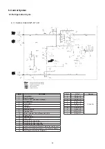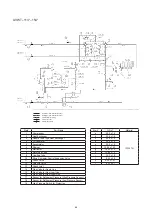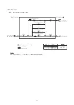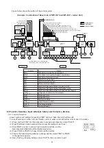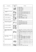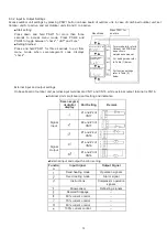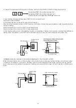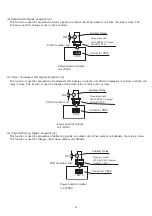
Figure below shows the outline of the control system.
(Example: Combination of Base Units, AVWT-190
*
to AVWT-
454*
+
Indoor Unit)
Symbol
Name
MC
1
DC Motor (for Inverter Compressor)
MC
2
AC Motor (for Constant Speed Compressor)
MOF
DC Motor (for Outdoor Fan)
MIF
Motor (for Indoor Fan)
MS
Motor (for Auto-Louver)
MD
Motor (for Drain Pump)
MV
Electronic Expansion Valve (for Indoor Unit)
MV
1
Electronic Expansion Valve (for Outdoor Unit)
MVB
Electronic Expansion Valve for Plate Heat Exchanger
CMC
1, 2
Magnetic Contactor for Compressor
SVA
Solenoid Valve
SVG
Solenoid Valve
RVR
1, 2
Reversing Valve
PSH
1, 2
High Pressure Switch
CH
1, 2
Crankcase Heater
CT
u, v
Current Sensor
Multiple Signals
Single Signal
Operation Signal
Wireless Remote
Control Switch
Remote
Control
MCU
Transmission Circuit
Remote
Control
MCU
Transmission Circuit
Wireless Transmission
Circuit
Remote Control Switch
Electrical Control
Expansion Valve
Drive Circuit
Relay
Drive
Circuit
MV
MD MS
MIF
Indoor Unit
Fan
Control
Circuit
Protection
Circuit
Indoor Unit
MCU
A D
Conversion
Circuit
A D
Conversion
Circuit
Transmission Circuit
Transmission Circuit
to Transmission Circuit of
Combination Outdoor Unit
Outdoor Unit
MCU
Electrical Control
Expansion Valve
Drive Circuit
Relay
Drive
Circuit
Inverter
Control for
Fan MCU
MV
1
CTu, v
CH
1
CH
2
MVB
MOF
CT
2
RVR
1, 2
SVA
PSH
2
PSH
1
MC
2
SVG
CMC
1
CMC
2
MC1
Outdoor Unit
To Transmission Circuit of the Switch Box,
the next Indoor Unit, or the next Outdoor Unit
Protection
Circuit
Inverter
Control
MCU
Inverter Power
Section
Thermistor for Inlet Air
Thermistor of Discharge Air
Thermistor for Gas Pipe
Thermistor for Liquid Pipe
Discharge Gas Pressure Sensor (Pd)
Suction Gas Pressure Sensor (PS)
Thermistor for Ambient Temperature “TA” (THM7)
Discharge Gas Thermistor “TD1” (THM8)
Discharge Gas Thermistor “TD2” (THM9)
*only for AVWT-136 to 170
Thermistor for Evaporation Liquid LineTemperature “TE” (THM10)
Thermistor for Evaporation Gas LineTemperature “TG” (THM11)
Thermistor for Super Cooling Temperature at Bypass Line “TBG” (THM23)
Thermistor for Super Cooling Temperature at Main Line “TCHG” (THM17)
Fin Thermistor
THM
*only for AVWT-1
14
to
1
54
only for AVWT-1
14
to
154
*
only for AVWT-1
14
to 1
54
*
6.3 Function Selection, Input & Output, Safety and Protective Devices
6.3.1 Function Selection
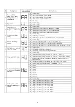
Access outdoor unit settings by pressing PSW1 button on base board of outdoor unit.
In case of combined outdoor unit, set Outdoor unit A to active, and set Outdoor units B and C to inactive.
(1) Press and hold PSW1 for three seconds to access spot inspection mode "CHEC"
.
(2) Press PSW4 two times to access function selection setting mode "Func"
.
(3)
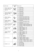
Press PSW1 one time to access function selection options, and the
seven-segment digital tube will be displayed as below
.
(4) Press PSW4 or PSW2 to choose function setting options
.
(5) Choose the function setting options to change, and then press PSW3 or PSW5
to change these options.
(6) Upon finishing changing settings, press PSW1 for three seconds to exit.
Item
Setting
69

