37
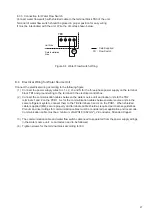
8.4 Electrical Wiring for Water Source Unit
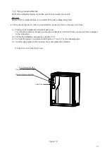
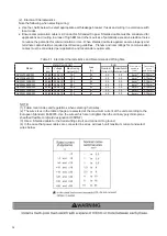
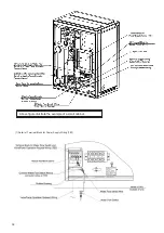
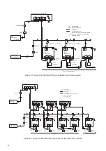
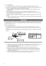
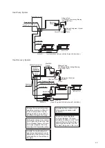
Connect the electrical wiring according to the following figure
(1) Connect the power supply wires to L1, L2, L3 and N for the three-phase power supply on the terminal
block TB1 and ground wiring to the terminal in the electrical control box.
(2) Connect the communication cables between the water source unit and indoor units to the TB2
terminals 1 and 2 on the PCB1. As for the communication cables between water source units in the
same refrigerant system, connect them to the TB2 terminals 3 and 4 on the PCB1. When shielded
cable is applied (M4), secure properly and terminate cable shield as required per Hisense guidelines.
Plenum and riser ratings for communication cables must be considered per application and local code.
Communication cable must be a minimum of AWG18 (0.82mm
2
), 2-Conductor, Stranded Copper.
(3) The communication cable and water flow switch cable need to separated from the power supply wirings
(4) Tighten screws for the terminal block according to IEC.
in the water source unit. Local codes need to be followed.
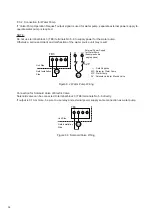
8.3.3 Connection for Water Flow Switch
Connect water flow switch with shielded cable to the terminal block TB3 of the unit.
Terminal of water flow switch should be placed in proper position for easy wiring
It must be interlocked with the unit. Wire the circuit as shown below.
TB3
5
6
7
8
FS
Unit Side
Field Installation
Side
: Field Supplied
FS : Flow Switch
Figure 8.4 Water Flow Switch Wiring
Summary of Contents for AVWW-114FKFW
Page 2: ......

