background image

48

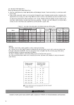
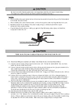
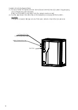
Do not apply excessive force to the stop valve after fully opening. Otherwise, the stop valve will blow out due 

to refrigerant pressure.  At the test run, fully open the stop valve. Otherwise, these devices will be damaged. 

(It is closed before shipment.)

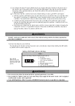
Caution for Opening Stop Valve

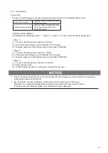
1. Do not apply an excessive force after fully opening the stop valve (Tightening Torque: < 5.0 N·m).

(This valve does not have a hard stop when opening, and allows for the complete removal of the valve

stem.)

2. Securely tighten the caps according to the torque specifications in Section 7.2.1 after each stop valve is

opened.

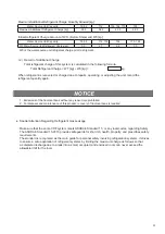
Hexagonal Wrench Size [mm]

Model 

Gas Valve Liquid Valve

76, 96

5

5

114

, 136, 154

10

170 - 190

9.3  Charging Work

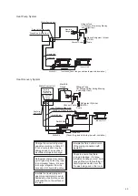
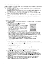
(1)  An additional refrigerant charge is required according to total piping length. Refer to Table 9.1.
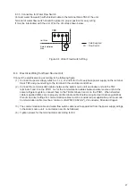
(2)  After vacuum pumping work, check that the high/low pressure gas valve (low pressure gas valve is for 

heat recovery system only), and liquid stop valve are fully closed. 

Charge the additional refrigerant from the access port of liquid stop valve (acceptable error must 

be within 0.5 kg).

(3)  After refrigerant has been charged, fully open the liquid stop valve and gas stop valves. 

Gas remaining at the O-ring or screw component may emit a hissing sound when removing the stop 

valve cap. However, this is not leaking gas.

(4)  If it proves impossible to dispense the specified (charged) quantity of refrigerant, follow the procedure 

below.

(a)  Fully open the stop valve at the gas line side (for heat recovery system, both stop valves of high/low 

pressure and low pressure side).

(b)  Operate the compressor in the cooling mode and charge the additional refrigerant from the access 

port of the liquid stop valve. An acceptable error must fall within 0.5 kg.  At this time, keep 

the liquid stop valve slightly open.

(c)  After the refrigerant is charged, fully open the liquid stop valve and the gas stop valve.
(d)  Carefully calculate any additional refrigerant quantity for charging. If the quantity of additional 

refrigerant is not correct, it might cause a compressor failure. The additional refrigerant must be 

charged in a liquid condition.

(e)  Refrigerant charge from the access port on the gas stop valve can lead to compressor failure. 

Be sure to charge refrigerant from the access port on the liquid stop valve.

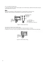
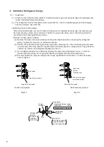
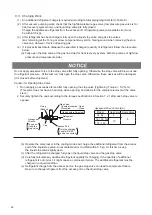
Refrigerant

Pressure

Stop Valve

Counterclockwise...Open

Clockwise...............Close

Only the charging

hose for R410A

can be connected.

Access Port

Cap

O-ring

(Rubber)

Hexagonal

Wrench

To open or

close the

stop valve

Closed before Shipment

Summary of Contents for AVWW-114FKFW

Page 1: ...WW 380FKFW AVWW 400FKFW AVWW 418FKFW AVWW 440FKFW AVWW 456FKFW AVWW 476FKFW AVWW 494FKFW AVWW 516FKFW AVWW 534FKFW AVWW 550FKFW AVWW 570FKFW IMPORTANT READ AND UNDERSTAND THIS MANUAL BEFORE INSTALLING...

Page 2: ......

Page 3: ...ce with our instructions EN 60335 1 EN 60335 2 40 EN 62233 EN 378 2 EN 61000 6 1 EN 61000 6 3 following the provisions of 2006 42 EC 2014 30 EU 2012 19 EU 2011 65 EU 2014 35 EU 2014 68 EU 2014 517 EU...

Page 4: ...act your distributor or contractor This manual provides common descriptions basic and advanced information to maintain and service this heat pump and heat recovery air conditioning unit which you oper...

Page 5: ...purchase order 3 The standard use for this unit is explained in these instructions Use of this equipment for purposes other than what it designed for is not recommended 4 Please contact your local ag...

Page 6: ...t 21 7 Refrigerant Piping Work 22 7 1 Piping Materials 22 7 2 Piping Connection Work 22 7 2 1 Stop Valve 22 7 2 2 Piping Connection Method 27 7 3 Piping Sizes from Water Source Units 30 7 3 1 Heat Pum...

Page 7: ...9 1 Leak Test 44 9 2 Vacuuming 47 9 3 Charging Work 48 9 4 Additional Refrigerant Charge Calculation 50 10 Test Run 52 10 1 Before Test Run 52 10 2 Test Run for Water Piping 53 10 3 Test Run for Water...

Page 8: ...n earthquake If the unit is not installed correctly injuries may occur due to a falling unit Use appropriate Personal Protective Equipment PPE such as gloves and protective goggles and where appropria...

Page 9: ...ed These products should not be installed in such locations Do not install the unit where water can seep into the unit or where there is high humidity that can affect the unit Installation Precautions...

Page 10: ...drop on the service panels of the water source unit Securely fasten the service panels Otherwise dust or water may enter the unit causing fire or electric shock Water source unit must be used with clo...

Page 11: ...tends to be affected by foreign matters such as moisture oxide film or other non condensables Perform the installation work with care to prevent moisture dust or different refrigerant from entering th...

Page 12: ...induction motor and large sized switch Regarding the cases mentioned above surge voltage may be inducted into the power supply cables for the packaged air conditioner due to a rapid change in power c...

Page 13: ...r or fuse is frequently tripped shut down the system and contact your service contractor Perform all electrical work in accordance with this manual and in compliance with all regulations and safety st...

Page 14: ...unit If any of these accessories are not packed with the unit please contact your distributor NOTICE mm ID Inner Diameter OD Outer Diameter Accessories Pipe Access ories Adapters at HP gas side Adapte...

Page 15: ...70 190 476 96 190 190 494 114 190 190 516 136 190 190 Model AVWW 456FKFW AVWW 476FKFW AVWW 494FKFW AVWW 516FKFW Capacity 534 154 190 190 550 170 190 190 570 190 190 190 Model AVWW 534FKFW AVWW 550FKFW...

Page 16: ...n the following places Doing so can result in an explosion fire deformation corrosion or product failure Explosive or flammable atmosphere Where a fire oil steam or powder can directly enter the unit...

Page 17: ...in the following figures Service and Installation Spaces Secure the service space when replacing parts or service maintenance access Single installation with refrigerant pipes from front side piping...

Page 18: ...ltiple installation with drain pipe from front side of unit Provide minimum of 500mm space for drain pipe from rear side of unit Top View Model L 76 96 114 and 136 820 154 170 and 190 1040 Unit mm Uni...

Page 19: ...belts by using shackles Angle of sling belts is more than 60 Sling Belts Do not apply any force to surface Both Sides Min 2m Top corners Attach four 15mm thick corrugated corner pads as shown Bottom...

Page 20: ...n and test run Damage and fire can result due to carelessness The concrete foundations are installed along the water source unit width direction Correct Min 100 Min 100 Front Side of Unit Front Side o...

Page 21: ...ote condensate drainage 4 Provide a strong level and stable foundation so that a The water source unit does not lean to one side b Sound from inside unit are minimal c The water source unit always rem...

Page 22: ...ly Install automatic air discharge valves at the higher position where air is likely collect and in order to discharge air in piping If air remains inside the water piping then it may decrease the ope...

Page 23: ...nd outlet of the water source unit Be sure to check the position of connection piping Do not connect inlet and outlet piping reversely Tighten securely the connection of water piping and socket with t...

Page 24: ...insula ion to keep the water piping cool and to prevent sweating of the piping Thermal loss may also occur If the water is frozen the plate heat exchanger of the water source unit may be busted Prepar...

Page 25: ...consumption is increased It is recommended to operate below the rated water flow rate 6 2 Water Flow Rate and Pressure Drop Model 76 96 114 136 154 170 190 Rated Water Flow Rate m3 h 4 60 5 76 6 90 8...

Page 26: ...flow switch is NOT proper non detectable plate heat exchanger may burst due to water freeze or compressor may damage due to increased pressure On the other hand if the water flow switch detection is e...

Page 27: ...t is also necessary to analyze the quality of water by checking pH electrical conductivity ammonia ion content sulfur content and others and to utilize treated water only if problem is encountered thr...

Page 28: ...O3 for 15 20 minutes When using any cleaning detergent sold in the market make sure that it does not cause corrosion to stainless steel and copper For details of cleaning method contact the manufactur...

Page 29: ...ping are properly connected to the equipment as specified in the installation instructions When handling the refrigerant be sure to wear leather gloves to prevent injuries Cautions for Refrigerant Pip...

Page 30: ...to the outside of the flare Do not apply any oil to the threads Tighten the liquid pipe flare nut to the specified torque while using a back up wrench to prevent damage to the unit Ensure that the fl...

Page 31: ...ng components within 15o CORRECT INCORRECT Example for Pipe Support Secure Liquid Pipes and Gas Pipes For Heat Pump System For Heat Recovery System Water Source Unit Indoor Unit Multi Kit Install Hori...

Page 32: ...96 22 2 9 52 Model AVWW FKFW 3 Pipes mm Model Gas Liquid Low Pressure High Low Pressure 76 96 19 05 9 53 114 136 12 70 25 40 154 190 25 40 19 05 22 20 22 20 15 88 Table 7 1 Piping Sizes of Water Sourc...

Page 33: ...cap diagram below 5 Remove the closing pipe piping cap from the brazing portion with a torch The stop valve will be damaged unless protected by a wet cloth or other means Release the gas inside the c...

Page 34: ...and check that no excessive force is applied to the stop valve 2 Follow the installation procedures in Section 7 2 1 3 Connect the piping in accordance with Figures 7 1 and 7 2 on the following page...

Page 35: ...ection for Liquid Line Accessory Pipe for Gas Line 170 190 114 136 76 96 154 Stop Valve for Liquid Stop Valve for Gas Not Used Accessory Pipe for Liquid Line Direct Connection for Gas Line Stop Valve...

Page 36: ...ssure Gas 170 190 76 96 114 136 154 Stop Valve for Liquid Stop Valve for High Low Pressure Gas Direct Connection for Liquid Line Direct Connection for High Low Pressure Gas Line Stop Valve for Low Pre...

Page 37: ...ssure Gas 15 88 19 05 22 2 22 2 22 2 Liquid 9 53 9 53 12 7 12 7 15 88 7 3 1 Heat Pump System 7 3 2 Heat Recovery System Refrigerant Piping To Indoor Units a Water Source Unit Refrigerant Piping To Ind...

Page 38: ...ng to the following torque M3 5 0 7 to 0 9 N m M4 1 0 to 1 3 N m M5 2 0 to 2 4 N m M6 4 0 to 5 0 N m M8 9 0 to 11 0 N m M10 18 0 to 23 0 N m Use the specified cables for wiring between the water sourc...

Page 39: ...ommunication errors When shielded cable is applied secure properly and terminate cable shield as required per Hisense guidelines Plenum and riser ratings for communication cables must be considered pe...

Page 40: ...nication Cable Switch Box I U Power Supply Wiring I U Switch Box Ground Wiring I U Switch Box Water Source Unit A S ELB 10 10 2 1 Heat Recovery System Heat Pump System Indoor Unit Indoor Unit Water So...

Page 41: ...uning Current A Nominal Current A Nominal Sensit ive Current mA Hz V AVWW 76FKFW 50 60 380 415 20 30 4mm2 AVWW 96FKFW 50 60 380 415 25 30 4mm2 AVWW 114FKFW 50 60 380 415 32 30 4mm2 AVWW 136FKFW 50 60...

Page 42: ...tion may occur if there is escaping gas Water Piping There is no effective electrical ground provided if hard vinyl piping is used Lightning Conductor The electrical potential of the earth increases w...

Page 43: ...or Solenoid Valve of Electric Valve Solenoid valve can be connected to terminal block 3 TB3 terminals No 5 6 directly If output is 0 1A or more be sure to use relay and external power supply same conn...

Page 44: ...d as required per Hisense guidelines Plenum and riser ratings for communication cables must be considered per application and local code Communication cable must be a minimum of AWG18 0 82mm2 2 Conduc...

Page 45: ...38 Above figure illustrate the example of a small cabinet 1 Detail of Terminal Block for Power Supply Wiring TB1...

Page 46: ...for Water Flow Switch and Valve Pump Operation Request Wiring TB3 2 Detail of Terminal Block for Communication Cable TB2 Inside of Unit Outside of Unit PCB1 TB2 Screw M3 5 Not Used This terminal is u...

Page 47: ...source units as shown in Figure 8 5 and 8 6 4 Connect the communication cables in the same refrigerant system unit If the refrigerant piping of indoor unit is connected to the water source unit also...

Page 48: ...ther refrigerant systems 9 Do not connect the power supply wiring to the terminal block for communication cable TB2 All the printed circuit boards in the same refrigerant system will be damaged 10 For...

Page 49: ...L3 1 2 3 4 1 2 A B TB2 1 2 A B TB2 TB1 L1 L2 N L1 L2 N L1 L2 N L1 L2 N L1 L2 N No 0 Indoor Unit No 1 Indoor Unit Distribution Box or Pull Box Distribution Box or Pull Box Distribution Box or Pull Box...

Page 50: ...2 CN16 1 3 pin Setting Before Shipment Setting of External Input and Output Function Function No Input Output 1 Fixing Heating Operation Mode Operation Signal 2 Fixing Cooling Operation Mode Alarm Sig...

Page 51: ...irection b Perform the work after warming the stop valve with a hair dryer etc when controlling the stop valve in a cold area The stop valve O ring will harden at low temperature causing the O ring ma...

Page 52: ...ulation up to the water inlet outlet root part of heat exchange and the water piping to prevent sweating and freezing Otherwise damage may be caused by freezing during low ambient temperature and ther...

Page 53: ...ndividually Make sure to insulate the union flare nut for the piping connection as well 2 Seal the gap between the bottom base or front piping cover and pipes with the insulation CAUTION If the gap is...

Page 54: ...to atmosphere level as less than 0 03 MPaG Step 2 1 Vacuum until the pressure reaches 1 mmHg 2 Pressurize with nitrogen up to 0 3 MPaG for 15 minutes 3 Release pressure to atmosphere level as less tha...

Page 55: ...e and gas stop valves Gas remaining at the O ring or screw component may emit a hissing sound when removing the stop valve cap However this is not leaking gas 4 If it proves impossible to dispense the...

Page 56: ...se difficulty with breathing or harmful gases would occur if a fire was being used in the room Stop Valve for Low Pressure Gas Manifold Gauge Vacuum Pump Nitrogen Tank for Nitrogen Blow during Brazing...

Page 57: ...Total Piping Length In piping chilled refrigerant Additional Charge kg 22 2 19 05 15 88 12 7 9 53 6 35 m m m m m m 0 30 0 24 0 15 0 09 0 04 0 02 This Example s Total Additional Charge kg Indoor Additi...

Page 58: ...operating or adjusting the unit record the refrigerant quantity again 1 Emissions of the fluorocarbons without any reason are prohibited 2 For disposal and maintenance of this product recovery of fluo...

Page 59: ...rent outflow is found and fixed Refer to Caution for Insulation Resistance for details Do not impress the voltage on the terminals for communication lines Water Source Unit TB2 1 2 3 4 Indoor Unit TB2...

Page 60: ...re positioned at their correct places 1 Close the gate valves to cut off water flow to the water source unit and circulate water within the common water piping After removing any foreign particles and...

Page 61: ...onnected indoor units the auto address function is not performed correctly due to incorrect wiring or electronic noise EMI Turn OFF the power supply and correct the wiring after checking the following...

Page 62: ...unit for a few seconds after running or stopping the compressor and so on It generates because of the pressure difference inside the compressor piping Therefore there is no problem with the unit Do N...

Page 63: ...wever the test run function of the water source unit is not canceled Check to ensure that the No 1 pin of DSW4 of the water source unit PCB is turned OFF If multiple indoor units are connected with on...

Page 64: ...Temperature o C Discharge Gas Temperature o C 8 Check Pressure Discharge Pressure MPa Suction Pressure MPa 9 Check Voltage Rated Voltage V Operating Voltage L1 L2 V L1 L3 V L2 L3 V Starting Voltage V...

Page 65: ...Abnormality of Outdoor Air Thermistor EconoFresh 16 Abnormality of Remote Sensor DOAS 17 Abnormality of Thermistor Built in Remote Controller DOAS 18 Indoor Fan Motor Abnormality of Indoor Fan System...

Page 66: ...Indoor Unit Incorrect Setting of Unit Model Code Incorrect Setting of Indoor Unit Model b1 Incorrect Setting of Unit and Refrigerant Cycle Number 64 or More Number is Set for Address or Refrigerant C...

Page 67: ...erter Compressor Automatic Reset Non Adjustable Over Current Inverter Current Protection Control A Fuse A Over Heat Automatic Reset Non Adjustable for 5sec o C for 10min o C For Fan Motor Electrical B...

Page 68: ...nger of air conditioner heat pump air Type compressor driven vapour compression thermostat off mode heating crankcase heater mode Item Indication if the heater is equipped with a supplementary heater...

Page 69: ...8 Qianwangang Road Economic Technical Development Zone Qingdao P R China http www hisense vrf com E mail export hisensehitachi com 1110154 Packing List Details Remarks 1 Set 1 pc 1 pc 1 pc Outdoor Uni...

Reviews: