52
10. Test Run
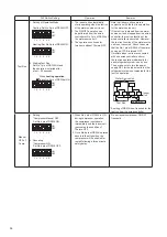
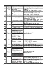
Test Run should be performed in accordance with Sections 10.2 and 10.3. Use Table 10.1 for recording the
Test Run.
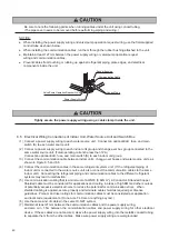
An electrical shock will occur if there is residual voltage.
Turn OFF power at the power supply completely before attempting any electrical maintenance work.
Verify that no residual voltage exists after turning OFF the power at the power supply.
10.1 Before Test Run
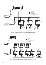
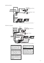
(1) Check to ensure that the refrigerant piping and communication lines between indoor and water source
units are connected into the same refrigerant system. If not, the result will be abnormal operation with
a potentially serious accident.
Verify that all DIP switch settings for the refrigerant system numbers (DSW1 and RSW1 for water
source unit and DSW5 and RSW2 for indoor unit) and the unit number (DSW6 and RSW1) for indoor
units are applicable to the system.
Depending on the indoor unit type RSW is different. Refer to the installation manual attached to each
indoor unit. Confirm that all DIP switch settings on the printed circuit board for indoor and water source
units are correct. Pay special attention to the setting for water source unit number, the refrigerant
system number, and end terminal resistance. Refer to Section 8, “Electrical Wiring.”
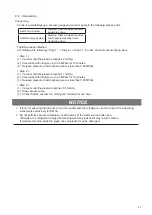
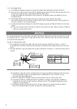
(2) Verify that electrical resistance is more than 1 megaohm, by measuring the resistance between ground
and the terminal for electrical components. If the electrical resistance is less than 1 megaohm, do not
operate the system until the source of electrical current outflow is found and fixed. (Refer to “Caution
for Insulation Resistance” for details.)
Do not impress the voltage on the terminals for communication lines (Water Source Unit: TB2 1, 2, 3,
4 / Indoor Unit: TB2 A, B, 1, 2 / Switch Box: TB2 1, 2, 3, 4). Otherwise, failure can result
.
(3) Verify that each wire, L1, L2, and L3, is correctly connected at the power supply.
If any one of those is incorrectly connected, the unit will not operate and the wired controller will
display the alarm code “05.” In this case, check and change the phase of the power supply according
to the spec sheet attached to the inside back surface of the service cover.
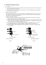
(4) Apply power to water source unit(s) at least 12 hours prior to operation of the system to allow for
adequate pre-heating of the compressor oil.
The water source unit does not operate for at most four hours after power supply
(Stoppage Code d1-22).
If operation resumes within four hours, release the protection control as follows:
1. Supply power to the water source unit.
2. Wait for 30 seconds.
3. Push PSW5 on the water source PCB for more than three seconds in order to release the d1-22.
If using a wired controller for release:
* Press and hold “Menu” and “Back/Help” simultaneously for at least 3 seconds. The test run menu
is displayed.
* Press “ ” or “ ” to select “Cancel Preheating Control”. Press “OK” and cancel the pre-heating
control.
For other controllers, refer to the manual attached to each controller.
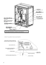
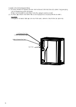
(5) Be sure to close the service cover at the front upper side when the test run is performed.
Do not activate the system until all issues have been examined and cleared.
Test Run of indoor unit: refer to the installation and maintenance manual which is attached to the indoor
unit and switch box.
Summary of Contents for AVWW-114FKFW
Page 2: ......

