background image

Installation instructions

15

Test the appliance by plugging the power supply cord in a correct  outlet of power source
before installation.

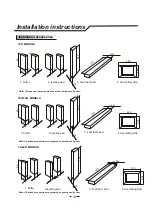
A clearance of 20 mm is advisable between the appliance cabinet and the wall. Fix the indoor air intake
panel with the cabinet by employing two screws which packed in the packing bag as shown in Fig.5. 

Put the buffers on the installation bracket as shown in Fig.6. Adjust the appliance as shown in Fig.4.
The leveling pads are employed to tilt the appliance in order that the indoor side is about (15

20) mm

higher than the outdoor side for fear the condensate overflow into the room.

lower part of 
installation bracket

buffer

Decorating strip

Fig.5

Fig.7

Fig.6

Fig.8

The seal foam pads are employed to prevent outside air from leaking into the room (Fig.7) and the
decorating strip is presented for aesthetical appearance as Fig.8.

A proper time-delay fuse should be employed in the power supply circuit.
For your personal safety, this air conditioner must be grounded. 
The extension of power supply cord is inadvisable.
Connect this air conditioner to its own individual wall receptacle to prevent itself and other appliances 
or household lights from causing a overload that could cause a power outage.

Condensate will form during the cooling or dry operation, user can choose drainage 
or no drainage. Remove the drainage tip and fix the drainage hose when drainage is chosen.
On the contrary, the condensate is splashed to cool the condenser so that the cooling capacity
and energy conservation is improved with a little high noise when no drainage is chosen.

1.Accessories

1.Accessories

1.Accessories

Installation steps

Drainage

Fuse and grounding

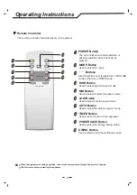
SWING

OFF

ON/

MODE

TIMER

FAN

SPEED

F

HR

SWING

OFF

ON/

MODE

TIMER

FAN

SPEED

F

HR

SWING

OFF

ON/

MODE

TIMER

FAN

SPEED

F

HR

HR

Version No. 819043545-01

Summary of Contents for HAWC12D

Page 1: ...ED F HR Window Room Air Conditioner User Manual HAWC12D Thank you very much for purchasing a air conditioner please read this User and Care Manual carefully before installing and using this appliance...

Page 2: ...y precautions Operating instructions Electrical specifications Part names Maintenance 5 8 Troubleshooting Installation instructions 11 12 Operation tips 9 1 PDF created with pdfFactory Pro trial versi...

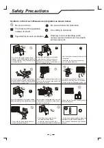
Page 3: ...sert a stick or similar to the unit Since the fan rotates at high speed this may cause an injury Do not repair the appliance by yourself If this is done incorrectly it may cause an electric shock etc...

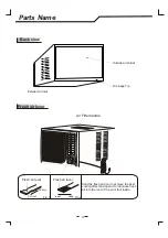
Page 4: ...rom that of the air conditioner you have selected Air Outlet Fig 1 Control Panel Power Cord Interior Air Inlet Grille Horizontal Air Vane Vertical Air Vane Front view Fresh air lever Exterior Air Inle...

Page 5: ...resh air door to achieve the best cooling effect and open it to introduce fresh air into the room if the air is foul inside Fresh air lever SHUT OPEN Fresh air lever Pull out Push in Fig 1 Fig 2 Outsi...

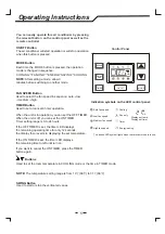
Page 6: ...maining operating time for only 12 seconds the display then reverts to displaying the set temperature If the ON TIMER is set the timer LED displays the remaining time to left until turn on If you want...

Page 7: ...o set or cancel a timer operation 4 HIGH Button Used to select mode high fan speed 5 MID Button Used to select medium mode fan speed 6 LOW Button Used to select Low mode fan speed 7 AUTO Button Used t...

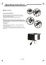
Page 8: ...it back into position Note Use 2 LR6 AA 1 5volt batteries Do not use rechargeable batteries Re place batteries with new ones of the same type when the operation becomes erratic If the replacement is d...

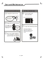
Page 9: ...nditioner is very dirty Unplug from power source after switch off the air conditioner Never use volatile substance such as gasoline or polishing powder to clean the appliance Clean and reinstall the a...

Page 10: ...urned Features of protector Caution The protective device will work at following cases Restarting the unit at once after operation stops or changing mode during operation you need to wait 3 minutes Co...

Page 11: ...ase consult a qualified electrician 4 The wall outlet must match the plug on the service cord supplied with the unit DO NOT use plug adapters or extension cord 5 The rating plate on the unit contains...

Page 12: ...rigerant in the air conditioner not a trouble The sound may be generated by the expansion or contraction of the front panel due to change of temperature Mist appears when the room air becomes very col...

Page 13: ...54 1 buffer 2 leveling pad 3 seal foam pad 4 decorating strip Note All above accessories are prepared or purchased by user 20 10 5 3 2 40 610 15 400 50 660 480 1 buffer 2 leveling pad 3 seal foam pad...

Page 14: ...h The metallic installation bracket should be constructed as fig 4 wooden strip Fig 1 Space for outdoor air intake Fig 3 The square hole should be smooth enough if the appliance is installed through a...

Page 15: ...ements 18 24K MODELS 90 510 710 20 30 thickness of wall Fig 1 710 20 510 90x20x710 910 90 180 A A A A wooden strip Space for outdoor air intake Fig 3 85 Fig 2 Fig 4 14 85 20 30 Fig 2 Fig 4 thickness o...

Page 16: ...trip is presented for aesthetical appearance as Fig 8 A proper time delay fuse should be employed in the power supply circuit For your personal safety this air conditioner must be grounded The extensi...

Page 17: ...Version No 4076 01 81904...

Page 18: ...lt built up of any part of the product including its parts or iii resulting from excessive use fair wear and tear iv resulting from poor installation including and not limited to positioning and exter...

Page 19: ...60 MONTHS IN HOME REPAIR WARRANTY Hisense Australia will provide its nearest service centre for repairs under warranty You will need to ensure that you have already called Hisense Warranty Centre and...

Reviews: