background image

pag. 23

Installation, Use and Maintenance Manual - HKFD1EC/C Series

English

NOTES: SIC reserves the right to modify data, pictures and all that is related to this printed matter without any notice.
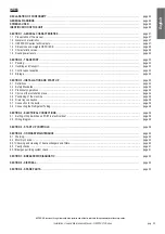
INDEX

DECLARATION OF CONFORMITY

...................................................................................................................................................

page 24

GENERAL WARNINGS

......................................................................................................................................................................

page 25

SYMBOLS USED

................................................................................................................................................................................

page 26

IDENTIFICATION OF THE UNIT

........................................................................................................................................................

page 26 

SECTION 1 - GENERAL CHARACTERISTICS

.................................................................................................................................

page 27

1.1 Presentation of the manual.........................................................................................................................................................

page 27

1.2 General characteristics ...............................................................................................................................................................

page 27

1.3 HKFD1EC/C series technical data .............................................................................................................................................

page 27

1.4 Dimensions and weights HKFD1EC/C .......................................................................................................................................

page 28

1.5 Characteristic curves ..................................................................................................................................................................

page 29

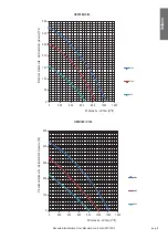
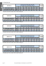
1.6 Sound power levels ....................................................................................................................................................................

page 32

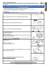
SECTION 2 - TRANSPORT

................................................................................................................................................................

page 33

2.1 Packing .......................................................................................................................................................................................

page 33

2.2 Handling and transport ...............................................................................................................................................................

page 33

2.3 Control upon reception ...............................................................................................................................................................

page 33

2.4 Storage .......................................................................................................................................................................................

page 33

SECTION 3 - INSTALLATION AND START UP

................................................................................................................................

page 33

3.1 Definitions ...................................................................................................................................................................................

page 33

3.2 Safety Standards ........................................................................................................................................................................

page 33

3.3 Preliminary operations  ...............................................................................................................................................................

page 34

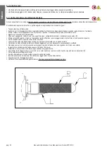
3.4 Choice of the installation place...................................................................................................................................................

page 34

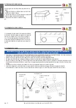
3.5 Positioning of the machine .........................................................................................................................................................

page 35

3.6 Drain tray connection..................................................................................................................................................................

page 35

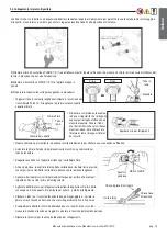
3.7 Connection to the ducts..............................................................................................................................................................

page 35

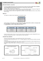
3.8 Connecting the Refrigerant Tubing.............................................................................................................................................

page 36

SECTION 4 - ELECTRICAL CONNECTIONS

....................................................................................................................................

page 38

4.1 Setting of Dip Switches on PCB1 in electrical box1 ...................................................................................................................

page 38

4.2 Wiring diagram............................................................................................................................................................................

page 39

SECTION 5 - START UP CONTROLS

...............................................................................................................................................

page 39

SECTION 6 - ORDINARY MAINTENANCE

.......................................................................................................................................

page 40

6.1 Warning.......................................................................................................................................................................................

page 40

6.2 Monthly checks ...........................................................................................................................................................................

page 40

6.2.1 Checking and cleaning of heat exchangers and filters...............................................................................................................

page 40

6.3 Yearly checks .............................................................................................................................................................................

page 41

6.3.1 Bioxigen purifying system check ................................................................................................................................................

page 41

SECTION 7 - BREAKDOWN DIAGNOSTIC

......................................................................................................................................

page 42

SECTION 8 - DISPOSAL

....................................................................................................................................................................

page 42

SECTION 9 - SPARE PARTS

.............................................................................................................................................................

page 43

Summary of Contents for HKF-100D1EC/C

Page 1: ...MANUALE DI INSTALLAZIONE USO E MANUTENZIONE INSTALLATION USE AND MAINTENANCE MANUAL HKF D1EC C UNIT DI RECUPERO CALORE ENERGY RECOVERY UNITS...

Page 2: ...al ricevimento pag 12 2 4 Stoccaggio pag 12 SEZIONE 3 INSTALLAZIONE E MESSA IN SERVIZIO pag 12 3 1 Definizioni pag 12 3 2 Norme di sicurezza pag 12 3 3 Operazioni preliminari pag 13 3 4 Scelta del lu...

Page 3: ...i di tensione Direttiva 2011 65 UE del Parlamento Europeo e del Consiglio del 8 giugno 2011 sulla restrizione dell uso di sostanze pericolose nelle apparecchiature elettriche ed elettroniche RoHS 2 Di...

Page 4: ...ibretto esclusa qualsiasi responsabilit contrattuale ed extracontrattuale della Ditta Costruttrice per danni causati a persone animali o cose da errori di installazione di regolazione e di manutenzion...

Page 5: ...i composti gassosi e o particelle solide L utilizzo della stessa per scopi diversi da quelli previsti e non conformi a quanto descritto in questo manuale far decadere auto maticamente qualsiasi respon...

Page 6: ...di regolazione a solenoide filtro sonde a contatto sulla linea del liquido e del gas sonde NTC a monte e a valle del flusso d aria Accessorio sistema di sanificazione Bioxigen attivo all accensione d...

Page 7: ...3 C BS 40 UR 11 C BS 45 UR condensazione 40 C 7 Aria ingresso batteria 28 5 C BS 50 UR evaporazione 7 C Modello Model Dimensione Dimension mm Peso netto lordo Weight net gross Kg Dimensioni imballo Pa...

Page 8: ...0 50 100 150 200 250 300 0 100 200 300 400 500 600 Pressione statica utile External static pressure Pa Portata aria Air flow m3 h 0 50 100 150 200 250 300 350 0 100 200 300 400 500 600 700 800 900 Pre...

Page 9: ...0 200 250 300 350 0 200 400 600 800 1000 1200 Pressione statica utile External static pressure Pa Portata aria Air flow m3 h 0 100 200 300 400 500 0 200 400 600 800 1000 1200 1400 Pressione statica ut...

Page 10: ...ale di Installazione Uso e Manutenzione Serie HKFD1EC C 0 50 100 150 200 250 300 350 400 0 200 400 600 800 1000 1200 1400 1600 Pressione statica utile External static pressure Pa Portata aria Air flow...

Page 11: ...band frequencies Lw globale Total Lw Hz 63 125 250 500 1000 2000 4000 8000 Canale di mandata Supply duct dB A 45 8 52 4 59 4 58 8 58 0 58 2 52 0 46 9 65 2 Canale di espulsione Exhaust duct dB A 44 8...

Page 12: ...per gli scopi concepiti UTILIZZATORE OPERATORE L utilizzatore o operatore la persona fisica che stata autorizzata dall utente a operare con la macchina PERSONALE SPECIALIZZATO Come tali si intendono q...

Page 13: ...documentazione Trasportare la sezione imballata il pi vicino possibile al luogo di installazione Non sovrapporre attrezzi o pesi sull unit imballata 3 4 Scelta del luogo d installazione Posizionare i...

Page 14: ...e di estremit E preferibile dare a questi canali una piccola inclinazione per evitare in ogni caso che l acqua possa risalire fino alla macchina 3 5 Posizionamento della macchina Qui di seguito sono i...

Page 15: ...e importante e dev esser svolta attentamente per ottenere una connessione affidabile Smontare le ghiere flare dai tappi presenti sulla macchina e posizionarle sul tubo da innestare Eseguire la cartell...

Page 16: ...ghe incontrollate di refrigerante E consigliabile utilizzare una chive con lunghezza del braccio di 200mm Assicurarsi di utilizzare le ghiere fornite con le macchine oppure in alternativa raccorderia...

Page 17: ...corrisponde alla capacit dell unit interna Italiano SEZIONE 4 COLLEGAMENTI ELETTRICI I collegamenti elettrici ai quadri di comando devono essere effettuati da personale specializzato secondo gli schem...

Page 18: ...FERENTIAL MAGNETOTHERMAL SWITCH Vm red GND black Vcc white Vsp yellow FG blue M1 Vm red GND black Vcc white Vsp yellow FG blue M2 Running signal Fault signal A TRATTEGGIO SONO RAPPRESENTATI I COLLEGAM...

Page 19: ...rato Rimuovere i due filtri facendoli scorrere sulle apposite guide PULIZIA DEI RECUPERATORI Aspirare con aspirapolvere l eventuale polvere che pu essersi depositata all interno dei recuperatori e ver...

Page 20: ...perficie piana svitare delicatamente il condensatore al quarzo C Sfilare la rete R esterna al tubo se l operazione risulta difficoltosa ruotare leggermente la rete attorno al condensatore al quarzo Pu...

Page 21: ...ttostimate Ostruzioni nelle canalizzazioni Velocit di rotazione selezionata troppo bassa o tensione di alimentazione non di targa Rumorosit Portata eccessiva Usura o cricche nei cuscinetti Ventilatore...

Page 22: ...H0650 VT000GIRMICH0650 PR000E000MICH065 80 CF0P30MICH080050 CF0M90MICH080480 MTE00000MICH0650 VT000GIRMICH0650 PR000E000MICH080 100 CF0P30MICH100050 CF0M90MICH100480 MTE00000MICH1000 VT000GIRMICH0100...

Page 23: ...Control upon reception page 33 2 4 Storage page 33 SECTION 3 INSTALLATION AND START UP page 33 3 1 Definitions page 33 3 2 Safety Standards page 33 3 3 Preliminary operations page 34 3 4 Choice of the...

Page 24: ...thin certain voltage limits Directive 2011 65 EU of the European Parliament and of the Council of 8 June 2011 on the restriction of the use of hazardous substances in electrical and electronic equipme...

Page 25: ...ion of conformity of installation workmanlike that is in compliance with the regulations in force and with the indi cations of this handbook The distributor Company does not answer to possible damages...

Page 26: ...ere the air is mixed and or altered by other gaseous com posites and or solid particles The use of the same for different purposes from those envisioned not conform to that described in this manual wi...

Page 27: ...n at fans running able to do an efficient antibacterial treatment ensuring a perfect healthi ness of supplied air Built in electric box equipped with PCB to control internal fan speed and to interconn...

Page 28: ...40 11 C DB RH 45 condensing temp 40 C 7 Air inlet condition 28 5 C DB RH 50 evaporating temp 7 C Modello Model Dimensione Dimension mm Peso netto lordo Weight net gross Kg Dimensioni imballo Packing...

Page 29: ...50 100 150 200 250 300 0 100 200 300 400 500 600 Pressione statica utile External static pressure Pa Portata aria Air flow m3 h 0 50 100 150 200 250 300 350 0 100 200 300 400 500 600 700 800 900 Press...

Page 30: ...50 200 250 300 350 0 200 400 600 800 1000 1200 Pressione statica utile External static pressure Pa Portata aria Air flow m3 h 0 100 200 300 400 500 0 200 400 600 800 1000 1200 1400 Pressione statica u...

Page 31: ...ale di Installazione Uso e Manutenzione Serie HKFD1EC C 0 50 100 150 200 250 300 350 400 0 200 400 600 800 1000 1200 1400 1600 Pressione statica utile External static pressure Pa Portata aria Air flow...

Page 32: ...d frequencies Lw globale Total Lw Hz 63 125 250 500 1000 2000 4000 8000 Canale di mandata Supply duct dB A 45 8 52 4 59 4 58 8 58 0 58 2 52 0 46 9 65 2 Canale di espulsione Exhaust duct dB A 44 8 51 9...

Page 33: ...rented the unit and that uses it for the conceived purpose USER OPERATOR The operator or user is the physical person who has been authorised from the customer to operate with the machine SPECIALISTIC...

Page 34: ...ion and the relevant documentation are included Transport the packed section as close as possible to the installation place Do not put tools or weights over the packed unit 3 4 Choice of the installat...

Page 35: ...ns of the machine in the atmosphere it is advised to interpose an antivi brating joint between the air outlets and yhe ducts The electrical continuity between duct and machine must however be guarante...

Page 36: ...process is important and should be done carefully to make a good flare Be sure to keep any con taminants moisture dirt metal filings etc from entering the tubing Remove the flare nut from the unit an...

Page 37: ...hat is used must be of the correct wall thickness as shown in the table below Because the pressure is approximately 1 6 times higher than conventional refrigerant pressure the use of ordinary flare nu...

Page 38: ...a section which is adapted to the engaged power and in the respect of the local norms Their dimension must however allow to realize a voltage drop of less than 3 during the starting phase 4 1 Setting...

Page 39: ...cc white Vsp yellow FG blue M1 Vm red GND black Vcc white Vsp yellow FG blue M2 Running signal Fault signal A TRATTEGGIO SONO RAPPRESENTATI I COLLEGAMENTI DA EFFETTUARSI A CURA DELL INSTALLATORE DASHE...

Page 40: ...andle Take the hexagonal heat exchangers out through the proper handles Remove the 2 filter by making them scroll on the slides CLEANING OF THE HEAT EXCHANGERS Remove with the vacuum cleaner the dust...

Page 41: ...until the quartz capacitor is fully out of the unit Unlock the electric connector After laying the module on a flat surface unscrew carefully the quartz capacitor C Remove the external net R if it sho...

Page 42: ...the volta ge correspond to that of the nameplate The rotor turn backwards Noise Excessive air flow Wear or crack in the pads Unbalanced fan Foreign bodies in the case Strong vibrations Unbalanced impe...

Page 43: ...00E000MICH065 80 CF0P30MICH080050 CF0M90MICH080480 MTE00000MICH0650 VT000GIRMICH0650 PR000E000MICH080 100 CF0P30MICH100050 CF0M90MICH100480 MTE00000MICH1000 VT000GIRMICH0100 PR000E000MICH100 130 Model...

Page 44: ...i modificare dati fotografie e quant altro riportato in questo stampato senza preavviso NOTES HISENSE reserves the right to modify data pictures and all that is related to this printed matter without...

Reviews: