background image


HME8C55S 


User Manual 

Read the User Guide thoroughly before 
using Hisense LCD monitor and keep it 
properly for future reference. 


RSAG2.025.7186SS B Version  

Website: www.hisense.cn 

Hisense LCD Monitor


Summary of Contents for HME8C55S

Page 1: ...HME8C55S User Manual Read the User Guide thoroughly before using Hisense LCD monitor and keep it properly for future reference RSAG2 025 7186SS B Version Website www hisense cn Hisense LCD Monitor...

Page 2: ...violations of the safety precautions and use instructions of the User Guide Hisense Group Service Hotline 4006111111 Hisense Group Installation Hotline 4008011111 Hisense service quality supervision t...

Page 3: ...r socket Use qualified sockets that have passed national safety certification Protect the power lead Put the power line in a place to prevent it from being stepped on or squeezed by objects above or a...

Page 4: ...or a long time disconnect the monitor from the power socket to avoid damage to the monitor caused by transient voltage To completely power off the monitor remove the power plug from the power socket D...

Page 5: ...rom the appearance of the actual product The information in this document is subject to change without notice This document provides instructions on correctly installing and using the LCD monitor Plea...

Page 6: ...nitor Front View 9 Monitor Input and Output Interfaces 10 Definition of Monitor Connector Pins 12 Operational Instructions and Function Adjustment 14 Power on off 14 Power Indicator Status 14 Button L...

Page 7: ...rts 3G SDI loopthrough I O simultaneous display of data from multiple signal sources and automatic display mode adjustment With the built in Picture by Picture PBP and Picture in Picture PIP functions...

Page 8: ...VGA x 1 SOG x2 3G SDI HD SDI x 1 Output signal interfaces HDMI x 1 3G SDI HD SDI x 1 Interaction interface RS485x2 Power supply Input voltage 220 V 50 Hz Typical power 220 W Machine dimension W x H x...

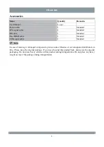
Page 9: ...able 1 Standard Note In case of missing or damaged components please contact Hisense or our designated distributors in time Please keep the original package If you need to send this product back pleas...

Page 10: ...ping off the bracket or support arm If the equipment is connected to a support arm do not use the equipment as a handle to move the equipment For instructions on how to move support arms connected to...

Page 11: ...installation the length of an M6 screw fixed to a wall mounted hole on the monitor rear cover is 8 10 mm Excessively long screws will cause irreparable damage to the monitor CAUTION Use support arms a...

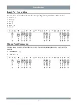
Page 12: ...sources to the corresponding video input interface of the monitor 1 HDMI IN 2 SDI IN 3 DVI 4 DP 5 SOG 6 VGA Output Port Connection Connect one or more available video receivers to the corresponding vi...

Page 13: ...with the monitor to the AC power supply interface of the monitor Protective Grounding Use an AWG18 wire with the maximum cable length approved by national regulations to connect the protective groundi...

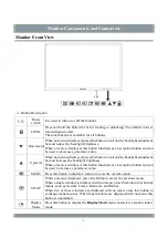
Page 14: ...ed press this button to call out the backlight adjustment bar and increase the backlight brightness When a menu is displayed this button functions as a navigation button and can be used to increase a...

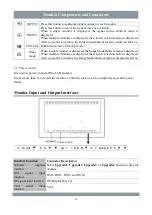
Page 15: ...ayed the Image Mode shortcut menu is displayed When multiple windows are displayed the window selection menu is displayed After you select a window the Image Mode shortcut menu is displayed after 3s P...

Page 16: ...interface HDMI OUT SOG signal input interface SOG 1 and SOG 2 Type B USB debugging interface USB 1 and USB 2 RS485 control signal input and output interface RS485 Note There are two RS485 interfaces w...

Page 17: ...d 18 5 V min 0 055 A 5 TMDS Data1 Shield 12 TMDS Clock 19 Hot Plug Detect 6 TMDS Data1 13 CEC 7 TMDS Data0 14 Reserved Simple illustration of the DVI signal input port DVI Port Definition Table DVI pi...

Page 18: ...AUX CH p 6 ML_Lane 2 p 16 GND 7 ML_Lane 1 n 17 AUX CH n 8 GND 18 Hot Plug 9 ML_Lane 1 p 19 Return 10 ML_Lane 0 n 20 DP_PWR 3 3 V 500 mA Simple SDI interface illustration SDI definition SDI pin defini...

Page 19: ...using a button you must unlock the button first Button unlocking When all the buttons are locked press and hold the LOCK button 3s to unlock all the buttons In this case the indicator changes to white...

Page 20: ...mall PIP Three Mode1 Three Mode2 Quad Mode SWAP Image Freezing Freeze and Normal Image Rollovers Normal Rotation and Mirror Image Rotating Normal Rotate Left and Rotate Right Windows Window 1 Window 2...

Page 21: ...m Left Upper Right Bottom Right and Center Time out 10s 20s 30s 60s and 120s System Settings HDMI Output Resolution 1920x1080P 60 Hz 3840x2160P 60 Hz Power Saving Enable and Disable Monitor Info Model...

Page 22: ...nnected signal source Restart the PC or the connected signal source device The image is blurred or has interference stripes or obvious color edges on characters Check whether wiring is secure It is re...

Page 23: ...isasters or improper maintenance by a third party other than Hisense and authorized distributors The product ages because it has been used with brightness above the recommended value in the User Guide...

Page 24: ...ion 3 1 or the medical electrical system requirements of Table BBB 201 in IEC 60601 1 1 The electromagnetic waves emitted by power supply equipment may affect the use of the LCD monitor and damage it...

Page 25: ...st harmful interference when the device is used in residential installation environments This device can generate utilize and radiate RF energy If it is not installed and used according to this manual...

Page 26: ...nt protection service life mark printed on the nameplate and storage box of this product indicates that the environment protection service life of electrical and electronic products is 10 years Names...

Page 27: ...returned product to indicate that the product has been purified If the returned product does not provide such external purification label and or such description is lost the seller or authorized servi...

Page 28: ...l rights reserved Without written permission by Hisense this document or any part of it shall not be copied in any form or in any method such as images and electronic or mechanical forms including pho...

Page 29: ...meets the requirements of Part 15 of FCC regulations Class A or Class B This device has been certified by Canadian and American UL regulations This device has been certified by CCC regulations This de...

Page 30: ...ical and Electronic Equipment WEEE Directions Direct current DC Power on Power off Grounding device EU authorized representative information The terminal of the device places different parts of the sy...

Page 31: ...1080 60 Hz 1920 x 1080 60 Hz 1920 x 1080 60 Hz 1080 59 94i 1920 x 1080 59 94 Hz 1920 x 1080 59 94 Hz 1920 x 1080 59 94 Hz 1080 60i 1920 x 1200 60 Hz 1920 x 1200 60 Hz 1920 x 1200 60 Hz 1080 50i 2048...

Page 32: ...Annex Appendix B Monitor Size Unit mm 27...

Page 33: ...Co Ltd Address North 3F Outsourcing Center of Software Park No 169 Songling Road Laoshan District Qingdao P R China Hisense national customer service hotline 4009940707 Hisense Group service supervis...

Reviews: