background image


Appendix: Installation

8

2. INSTALLATION LOCATION

2.1 Indoor unit

2.2 Outdoor unit

!

!

WARNING

WARNING

Maintain  the  required  space 

around  the  appliance  to 
prevent overheat.

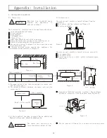
The location for installation of the appliance should not 

be in an area with the following:

    Direct sunlight

    Heat resource

    Inflammable gas

    Thick oil fog

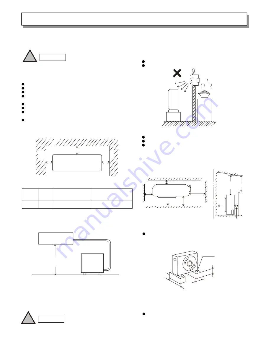
The appliance should be installed in an area,

    Where the inside space can be evenly conditioned, or

    Which is strong enough for the appliance, or,

   Having the shortest distance for the copper tubes and 

water drain hose, and

    Having  desired  space  around  the  appliance  for 

maintenance and ventilation.(Figure 1)

Min. 5cm

Min. 5cm

Min. 5cm

Figure 1

Tube arrangement

L           H         Added Refrigerant       Provided Tube(M)

                                   (g/m)

10

7

20

4

L: Maximum length of the tube connecting the indoor unit 

and the outdoor unit.

H: The height difference between the indoor unit and the 

outdoor unit.

Tube length(L)

Height difference(H)

Indoor unit

Outdoor 

unit

* If the length of the tube is exceed 7m, an additional 

20g/m of refrigerant  should be added per 1m.

Figure 2

The  indoor  unit  should  not  be 
installed below a height of 1.8m.

The outdoor unit should be installed away from the 

following:

   Heat source and fan exhausting (Figure 3);
   Director sunlight;

                                                                  
Figure 3

The outdoor unit should be installed in an area with,

   Cool temperature;

   Good ventilation;
   Desired space for air inlet, outlet and maintenance

    (Figure 4)

2m  

2m  

Air inlet

Min. 10cm

Min. 10cm

Min. 40cm

Min.10cm

Air inlet

Ground

Valve side
Min. 25cm

Top obstacle

Air outlet

Ai

ou

tl

et

Ob

st

ac

le

Figure 4

2

   Strong base (10x10cm  concrete or alike). The appliance 
    should be placed not less than 10cm high (Figure 5).

    Fix the base with firm bolts to reduce vibration and noise.

22

Concrete or alike

Firm bolts(4)

Min. 10cm

Abo t 

10cm

u

bo

40

A

ut 

cm

Figure 5

Summary of Contents for KF-1802GWE

Page 1: ......

Page 2: ...with in a 12 hour period 1 Hour OFF Timer This timer can be set to automatically turn off the unit after one hour Night Setback Pressing this SLEEP button changes the setting of the room temperature...

Page 3: ...21 5 4 Wrapping the tubes 1 Tie the two refrigeration tubes including electrical wire if permitted as regulated water drainage hose with white tape 2 Wrap half of the tubes outside the room starting f...

Page 4: ......

Page 5: ...ning 1 6 Tips for energy saving 1 8 The symbol refers to a hazard or an unsafe practice which can result in severe personal injury or death The symbol refers to a hazard or an unsafe practice which ca...

Page 6: ...is mounted Never use store gasoline or other flammable vapor or liquid near the air conditioner it is very dangerous The air conditioner has no ventilator for intaking fresh air from outdoors You mus...

Page 7: ...rs which remove dust Conditioned air is blown out of the air conditioner through the air outlet The wireless remote control unit controls power ON OFF operation mode selection temperature fan speed ti...

Page 8: ...s when the air conditioner is in the operation mode But the compressor may not run at this time This lamp lights when the system is being controlled by the timer REMOTE CONTROL receiver POWER lamp TIM...

Page 9: ...Displayed when sleep mode is running Displayed when indoor unit sensor is in use Symbols 1 Operation mode AUTO COOL MILD DRY FAN 2 Fan speed Automatic operation HIGH MEDIUM LOW 3 Set temperature 4 Tim...

Page 10: ...you press the buttons on the remote control unit the mark a p p e a r s i n the display to transmit the setting changes to the receiver in the air c o n d i t i o n e r A temperature sensor inside the...

Page 11: ...ioner stop at the set time This button is used to set cancel the time at which you wish the air conditioner to go on or off Use this button to select AUTO DRY or COOL mode When this setting is selecte...

Page 12: ...it more than 1 month take out the batteries How to Use the Remote Control unit When using the remote control unit always point the unit s transmitter head directly at the air conditioner s Remote Cont...

Page 13: ...difference between the actual room temperature and the temperature setting Press the FLAP button and set the airflow direction as desired STEP 1 STEP 2 STEP 3 STEP 4 STEP 5 AUTO Operation with the Re...

Page 14: ...able level Cooling mode When difference between room FAN SPEED temperature and set temperature is RT T 3 High T 3 RT T 1 Medium RT Low Mild drying mode When difference between room FAN SPEED temperatu...

Page 15: ...o longer match If this happens shut off the unit wait for the flap to close and then turn on the unit again the flap position will now be normal again Do not have the flap pointed down during cooling...

Page 16: ...tically Hour Press the SLEEP button NOTE This function loses in automation or airflow mode In Cooling and DRY Mode When the night setback mode is selected the air conditioner automatically raises 0 th...

Page 17: ...mer SET button which advances the time displayed STEP 1 STEP 2 STEP 3 The display changes immediately to its status previous to timer setting but the indication remains To check the status of the time...

Page 18: ...ress the ON OFF operation button again The 1 Hour Timer function is now cancelled and the unit operates normally If while the 1 Hour Timer function is operating the 1HR TIMER button is pressed once to...

Page 19: ...m the remote control unit stops for more than ten minutes due to the loss of the remote control unit or other trouble the air conditioner will switch to the temperature sensor which is built into the...

Page 20: ...ts or harsh chemicals when cleaning the indoor unit Do not wipe the plastic casing using very hot water Some metal edges and the fins are sharp and may cause injury if handled improperly be especially...

Page 21: ...How to replace the anti mold filter The air cleaning filter removes dust and dirt from the air and reduces odors and smoke from tobacco Air Clean Filter not provided WARNING This air clean filter cann...

Page 22: ...ge is too low 4 Operation button is OFF 5 Batteries in remote control unit have run down O b s t r u c t i o n i n f r o n t o f condenser coil 1 Dirty or clogged air filter 2 Heat source or many peop...

Page 23: ...uct KF 1802GWE AC 220V 50Hz AC 198 242V 0 70 1 8kW 3 330m h R22 0 47kg 8m 80 10m kW Type Power source Range of the voltage Rated power input Capacity Air flow high Refrigeration dose consumption Maxim...

Page 24: ...1 5 1 3 5 1 3 5 1 2 3 1 2 1 2 1 2 1 2 ROOM COIL FLAP FM PULSE IN DISPLAY PRY SEC POWER TRAN SENSOR CONECTION WITH OUTDOOR UNIT DISPLAY PANEL FAN MOTOR CONTROL BOARD SENSOR YEL GRN BRN BLU BLK BLK BLK...

Page 25: ...insulate the outdoor unit and make sure there is no moisture on the appliance or on the floor When the appliance is installed on a damp or uneven area Make a flat concrete base and place the base unde...

Page 26: ...nd the outdoor unit H The height difference between the indoor unit and the outdoor unit Tube length L Height difference H Indoor unit Outdoor unit If the length of the tube is exceed 7m an additional...

Page 27: ...ole is to be drilled 3 3 Installation of the back cover 1 check with a spirit level that the back cover is installed horizontally Figure 8 2 fix the back cover to the wall with the screws provided Fig...

Page 28: ...tribution cover Figure 14 3 Connect the wire distribution terminals and corresponding terminals Figure 15 Figure 15 Figure 16 4 Check the connections and then fasten the distribution cover and replace...

Reviews: