Appendix: Installation
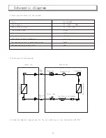
Figure 13
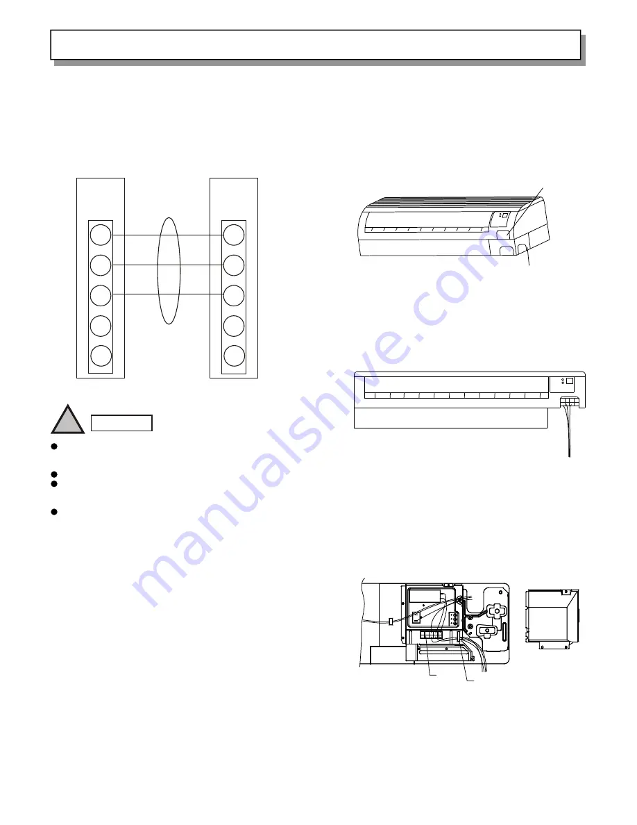
3.5 Wiring
(1)Before wiring, make sure the rated voltage indicated
on the nameplate conforms to the local power voltage.
(2)Wiring should be carried out in accordance with the
instructions on the electrical schematic diagram
(Figure 13).
1
2
3
4
5
1
2
3
4
5
Terminal
Panel of
the indoor
unit
Terminal
Panel of
the outdoor
unit
!
WARNING
Wiring for connection of the indoor unit and the
outdoor unit should be conducted in accordance with
local regulations.
Wiring connections must be fitted firmly.
The electrical wires should not be in contact with any
of the refrigeration tubes, compressor or other moving
parts or components.
The appliance must be connected to a good earth.
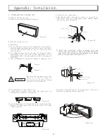
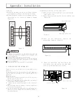
3.6 Wiring connection of the indoor unit
1) Hold pull and open the down right cover and the down
right grille cover.
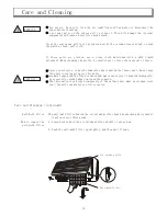
2) Release the screws and open the wire distribution cover
(Figure 14).
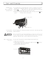
3)Connect the wire distribution terminals and
corresponding terminals .(Figure 15)
Figure 15
Figure 16
4) Check the connections and then fasten the
distribution cover and replace the down right
grille cover and down right cover finally.
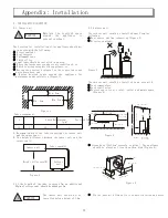
4. INSTALLATION OF THE OUTDOOR UNIT
Properly locate the outdoor unit as described by the
Section 2.
If the outdoor unit is to be mounted on the wall ,make sure
that the wall and the support are strong enough for the
appliance.
Wiring Connection
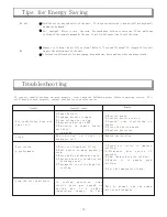
1) Release the fixing screws and take off the top cover
and the cover of control box.
2) Connect the terminals on the outdoor unit as required
in the Figure 13 and the Figure 16:
3) Always save an extra 10cm length of the electrical
cable:
4) Earth the appliance according to related regulations
of electrical engineering:
5) Fix the connected terminals with clips and replace the
side cover if the connection is assured according to
the wiring diagram:
24
Figure 14
Down right cover
Down right grille cover
Connection terminal
Clip
Cover of control box
POWER
TIMER

