background image

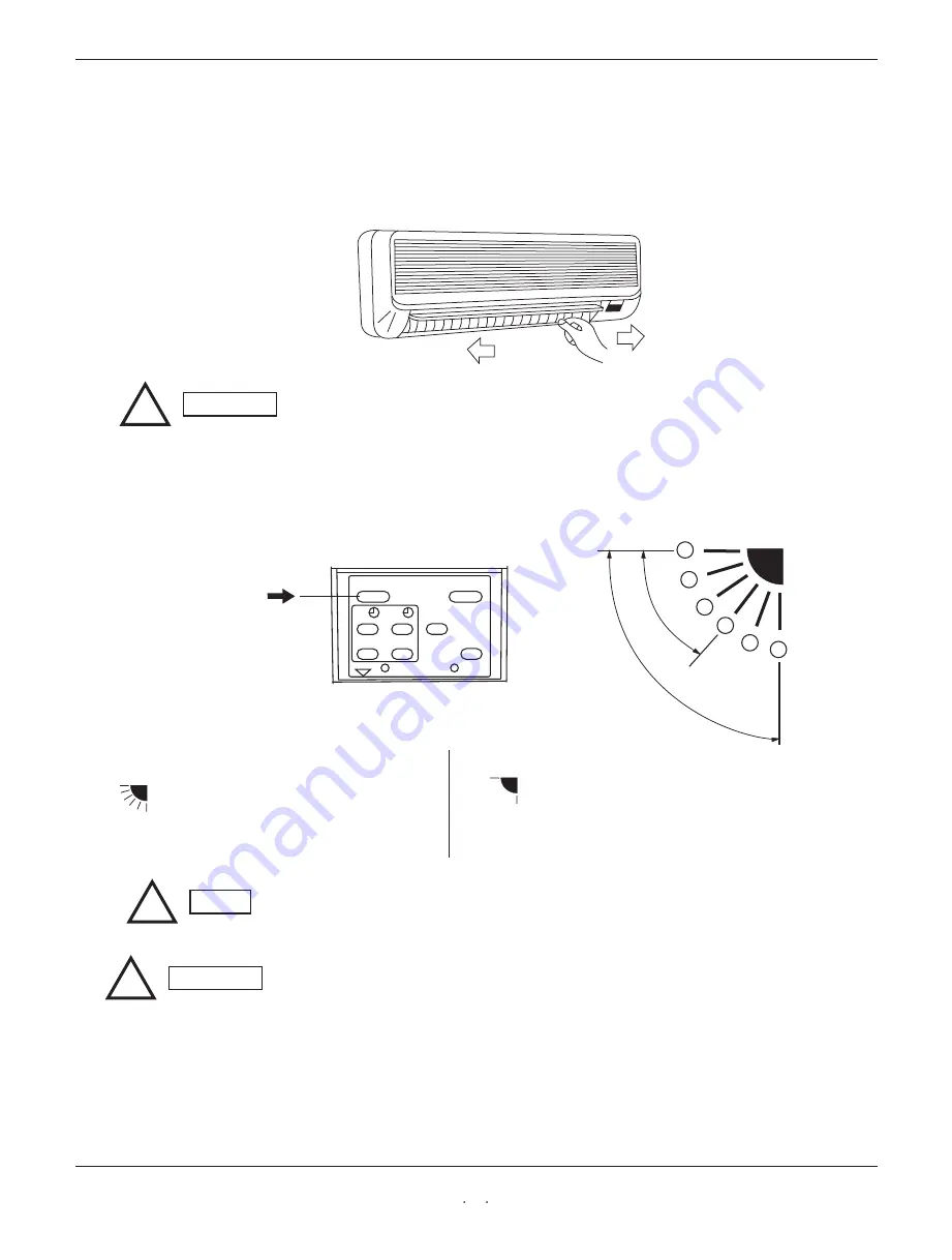
 Adjusting the Airflow Direction 

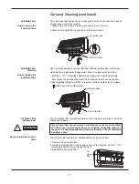
The horizontal airflow can be adjusted by moving the vertical vanes with your hands to the
 left or right.

2. Vertical                 

1. Horizontal

!

CAUTION

When the humidity is high, the vertical vanes should be in the front

position during the cooling or dehumidifying operation. If the vertical
vanes are positioned all of the way to the right or left, condensation may
begin to form around the air vent and drip down.

The vertical airflow can be adjusted by moving the flap with the remote control unit Do not 
move the flap with your hands.Confirm that   the remote control unit   has been turned on. 
Then, use the FLAP button to set either the sweep function or one of 
the six airflow direction settings. 

FLAP

ON

OFF

SET CANCLE

SLEEP

A/C SENSOR

ACL

BATTERY

FAN

SPEED

MODE

1

2

3

4

5

6

SWEEP                 

AUTO

A.Sweep function

                   The flap starts moving up and down to

                   deliver air over the sweep range.

B.Automatic Function


The flap moves up and down automatically

                  from 

 to 

 station.


!

NOTE


The flap automatically closes when the unit is off.

!

CAUTION

Use the FLAP button on the remote control   to adjust the position of the flap. 

       If you move the flap by hand, the flap position according to the remote control       

     and the actual flap position may no longer match.If this happens,shut off the 

     unit, wait   for   the flap   to close, and then turn on the unit again; the flap 

       position will now be normal again.

 Do not have the flap pointed down during cooling operation. Condensation     

       may begin to form around the air vent   and drip down.

11

Summary of Contents for KF 346GWE

Page 1: ...KF 346GWE KF 346GWE Hisense Corporation INSTRUCTION INSTRUCTION MANUAL MANUAL KF 256GWE KF 256GWE SPLIT TYPE AIR CONDITIONER SPLIT TYPE AIR CONDITIONER...

Page 2: ...EEP button changes the setting of the room temperature thermostat allowing you to set the temperature at whatever level that you feel comfortable Automatic and 3 step Fan Speed Auto High Medium Low Ai...

Page 3: ...hooting Schematic diagram Pardon not to inform you if the contents of the manual changes 1 2 3 8 16 18 18 19 WARNING CAUTION Alert Symbols The symbol refers to a hazard or an unsafe practice which can...

Page 4: ...this only for its intended purpose as described in this instruction manual 1 All wiring must conform to the local electrical codes 2 Each unit must be properly grounded 3 Wiring must be done by a qual...

Page 5: ...nsing Unit Drain Hose Air from the room is drawn into this section and passes through air filters which remove dust Conditioned air is blown out of the air conditioner through the air outlet The wirel...

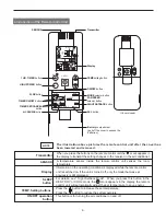
Page 6: ...p HIPOWER lamp This section picks up infrared signals from the remote control unit transmitter This lamp lights when the air conditioner is in the operation mode But the compressor may not run at this...

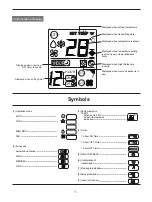
Page 7: ...is running Displayed when main unit sensor is in use Symbols AUTO SET TEMP SET TEMP C HOUR ON OFF AUTO AUTO 1HOUR 3 Introduction of Display 1 Operation mode AUTO COOL MILD DRY FAN 2 Fan speed Automati...

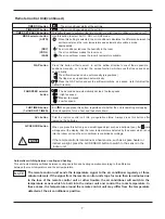
Page 8: ...ons on the remote control unit the mark appears in the display to transmit the setting changes to the receiver in the air conditioner A temperature sensor inside the remote control unit senses the roo...

Page 9: ...such as a ballpoint pen the mark will appear at the display And the room temperature is detected by the sensor which is built into the indoor unit and the air conditioner is controlled accordingly If...

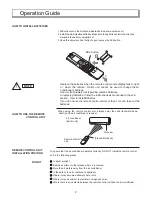
Page 10: ...when the remote control unit s display fails to light e NOTE When using the remote control unit always point the unit s transmitter head directly at the air conditioner s receiver To ensure that the...

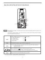
Page 11: ...s the MODE selector button and select the desired mode For dehumidifying operation For cooling operation For automatic operation For fan operation AUTO To start the air conditioner press the ON OFF op...

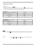
Page 12: ...el RT T 3 T 3 RT T 1 RT T 1 Cooling mode When difference between room temperatureand set temperature is FAN SPEED High Medium Low RT T 5 T 5 RT T 3 Rt T 3 Mild drying mode When difference between room...

Page 13: ...e sweep function or one of the six airflow direction settings FLAP ON OFF SET CANCLE SLEEP A C SENSOR ACL BATTERY FAN SPEED MODE 1 2 3 4 5 6 SWEEP AUTO A Sweep function The flap starts moving up and d...

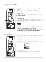
Page 14: ...ing and DRY Mode When the night setback mode is selected the air conditioner automatically raises the temperature setting 1 when 60 minutes have passed after the selection was made and then another 1...

Page 15: ...e indication remains To check the status of the timer while it is counting down press the timer SET button Cancellation procedure Press the CANCEL button once again 2 TIMER OFF mode Example HOUR HOUR...

Page 16: ...ressed once to cancel the function and then again the unit continues to operate for one hour from that point in time and then stops If the 1 HR TIMER button is pressed while the TIMER OFF function ope...

Page 17: ...signal to the air conditioner regularly at three minute intervals If the signal from the remote control unit stops for more than ten minutes due to the loss of the remote control unit or other troubl...

Page 18: ...unit to clean it This will damage the internal components and cause an electric shock hazard Clean the casing and grille of the indoor unit with a vacuum cleaner brush or wipe them with a clean soft...

Page 19: ...filter up into the unit and then lower the handle into the groove on the unit 2 After installing the anit mold filter press the locations marked by the arrows and close the air intake grille Air Clean...

Page 20: ...igh for cooling or too low for heating 6 Outdoor temperature is too low 7 Defrosting system does not work In heating or cooling operation some plastic parts may expand or shrink due to a sudden temper...

Page 21: ...consumption Maximum remote control range angle range Maximum length of the connect tube 19 KF 256GWE AC 220 230V 60Hz 920W 2500W 8m 80 15m 3 420m h R22 0 g 3 Permitted ambient temperature for the air...

Page 22: ...PULSE IN SW PRY SEC 0 1 2 3 4 5 TRANSFORMER SENSOR SENSOR PLUG EVAPORATOR TERMINAL TO OUTDOOR UNIT FLAP MOTOR CONTROL BOARD SWITCH ASSY YLW GRN YLW GRN BRN BRN BRN BRN BLU BLU RED BLK BLK WHT WHT BRN...

Page 23: ...UNIT POWER CABLE DRAINAGE ELBOW AIR FRESH FILTER INDOOR UNIT INSTRUCTION MANUAL INSTALLATION MANUAL REMOTE CONTROL UNIT BATTERY 1 1 1 1 1 1 1 1 2 OUTDOOR OUTDOOR OUTDOOR OUTDOOR INDOOR INDOOR INDOOR...

Reviews: