background image


Contents

1

Page

Alert symbol                                                                                                   

Caution statements                                                                                     

Composition of the air conditioner

Operation guide

Care and cleaning

Tips for energy saving

Troubleshooting

Schematic diagram                                                             

 Pardon not to inform you if the contents of the manual changes.

1

2

3

8

16

18

18

19

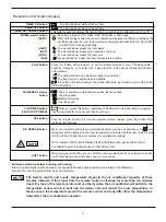
WARNING

CAUTION


Alert Symbols

The symbol refers to a hazard or an unsafe practice which can result in 
severe personal injury or death.

The symbol refers to a hazard or an unsafe practice which can result in 
personal injury or product damage.

Summary of Contents for KFR 2601GW/BPE

Page 1: ...KFR 2601GW BPE KFR 2601GW BPE INSTRUCTION INSTRUCTION MANUAL MANUAL KFR 2801GW BPE KFR 2801GW BPE SPLIT TYPE AIR CONDITIONER SPLIT TYPE AIR CONDITIONER Hisense Corporation...

Page 2: ...ontrols the output energy and perform the quick precise controlling of the room s temperature Air Sweep Control This function moves a flap up and down in the air outlet directing air in a sweeping mot...

Page 3: ...hooting Schematic diagram Pardon not to inform you if the contents of the manual changes 1 2 3 8 16 18 18 19 WARNING CAUTION Alert Symbols The symbol refers to a hazard or an unsafe practice which can...

Page 4: ...elp 2 The air conditioner is designed to give you comfortable room conditions Use this only for its intended purpose as described in this instruction manual 1 All wiring must conform to the local elec...

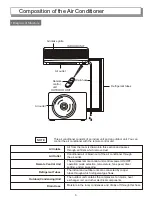
Page 5: ...nsing Unit Drain Hose Air from the room is drawn into this section and passes through air filters which remove dust Conditioned air is blown out of the air conditioner through the air outlet The wirel...

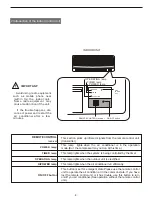
Page 6: ...IMER lamp HIPOWER lamp This section picks up infrared signals from the remote control unit transmitter This lamp lights when the air conditioner is in the operation mode But the compressor may not run...

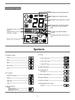
Page 7: ...r is in use Symbols 1 AUTO SET TEMP SET TEMP C A HOUR ON OFF AUTO AUTO 1HOUR 3 Introduction of Display Simultaneous use energy saving 1 Operation mode AUTO COOL HEAT MILD DRY FAN 2 Fan speed Automatic...

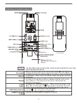
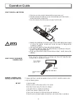
Page 8: ...en you press the buttons on the remote control unit the mark appears in the display to transmit the setting changes to the receiver in the air conditioner A temperature sensor inside the remote contro...

Page 9: ...e mark will appear at the display And the room temperature is detected by the sensor which is built into the indoor unit and the air conditioner is controlled accordingly If the remote control unit is...

Page 10: ...hen the remote control unit s display fails to light NOTE When using the remote control unit always point the unit s Transmitter head directly at the air conditioner s receiver To ensure that the air...

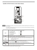
Page 11: ...DE selector button and select the desired mode For automatic operation For heating operation For dehumidifying operation For cooling operation For fan operation AUTO To start the air conditioner press...

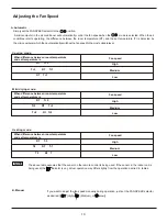
Page 12: ...om temperature and set temperature is Fan speed High Medium Low RT T 5 T 5 RT T 3 T 2 Rt T 3 Mild drying mode When difference between room temperature and set temperature is Fan speed High Medium Low...

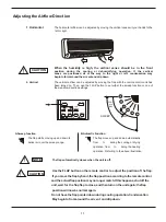
Page 13: ...ACL BATTERY FAN SPEED MODE SOFT 1 2 3 4 5 6 SWEEP COOL and DRY HEAT A Sweep function The flap starts moving up and down to deliver air over the sweep range B Automtic Function The flap moves up and do...

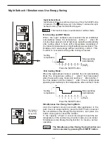
Page 14: ...tting temperature Stop operating Automatically Hour Press the SLEEP button B In heating Mode When the night setback mode is selected the unit automatically drops the temperature setting 2 when 1 hour...

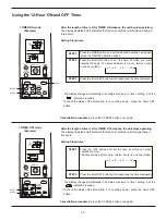
Page 15: ...g but the indication remains To check the status of the timer while it is counting down press the timer SET button Cancellation procedures press the CANCEL button once again 1 TIMER OFF mode Example H...

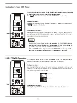
Page 16: ...is pressed once to cancel the function and then again the unit will continue to operate for one hour from that point in time and then stops If the 1 HR TIMER button is pressed while the TIMER OFF func...

Page 17: ...s because the COLD SRAFT PREVENTION SYSTEM is operating The POWER lamp also remains lit during defrosting or when the compressor has been turned off by the thermostat when the system is in the heating...

Page 18: ...bnormally WARNING 1 For safety be sure to turn the air conditioner off and also to disconnect the power before cleaning 2 Do not pour water on the indoor unit to clean it This will damage the internal...

Page 19: ...filter up into the unit and then lower the handle into the groove on the unit 2 After installing the anit mold filter press the locations marked by the arrows and close the air intake grille Air Clean...

Page 20: ...igh for cooling or too low for heating 6 Outdoor temperature is too low 7 Defrosting system does not work In heating or cooling operation some plastic parts may expand or shrink due to a sudden temper...

Page 21: ...cooling heating Air flow high Refrigeration dose consumption Weight indoor unit outdoor unit Maximum remote control range angle range Maximum length of the connect tube KFR 2801GW BPE AC 230V 8m 80 1...

Page 22: ...OOR UNIT WHT BLK RED RED CAPACITOR TO INDOOR 1 2 3 4 RECTIFIER TERMINAL BLK 1 1 2 2 ACIN1 ACIN2 ACOUT2 DC CAP COM COIL GAIKI RV DC ACOUT1 E SI 1 2 1 2 1 2 1 2 1 2 1 2 1 2 1 2 OLR W V U 10 WHT RED BLU...

Page 23: ......

Reviews: