background image

4


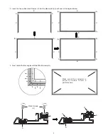
3.

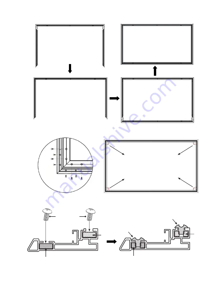
Insert the two vertical short frames (C) into the elbow joint (A) as shown in the diagram below.


4.

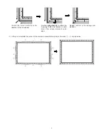
Next, fasten the four angles with the M5x6 Screws (H).


B

(A)

(A)

(A)

(A)

E

C

C

E

A

A

C

C


(A)

(A)

E

E

(A)

(A)

C

C

B

A

A

C

C


Make sure all four corners are 

properly in place to form a 

perfect square.

M5x6 Screws

(H)

H

H

A

A


A

A

Summary of Contents for Laser TV Display Screen

Page 1: ...INSTALLATION GUIDE Before you install this product read this guide completely and make sure you understand all of the content Hisense Laser TV Display Screen ENGLISH ES G1835M8...

Page 2: ...n It is not covered under warranty Don t touch the screen material to avoid leaving fingerprints Use gloves when handling the material Don t scratch the material as it will leave permanent markings on...

Page 3: ...Frame Spring inserted into the frame already 2 D1 Vertical Edge Trim short 2 D2 Top Edge Trim long 1 D3 Bottom Edge Trim long with logo 1 E Upper Frame Assembly 1 F Bottom Frame 2 G M3x6 Screws 20 H...

Page 4: ...abels and fasten the M5x14 Screws J 2 Insert the elbow joint A front side is up into each end of the horizontal frame B and upper frame assembly E as shown below B B F F B F J J J J B F A Sliding chut...

Page 5: ...e elbow joint A as shown in the diagram below 4 Next fasten the four angles with the M5x6 Screws H B A A A A E C C E A A C C A A E E A A C C B A A C C Make sure all four corners are properly in place...

Page 6: ...ial to prevent the screen from bending or rolling unevenly Each person should hold one end of the roll and slowly unroll the screen in a clockwise direction Figure 2 Tip Check the DOWNSIDE label on th...

Page 7: ...K to attach the spring to the hole located on the screen material s outer edge in the order of 1 1 2 2 3 3 4 4 then 5 5 6 6 7 7 8 8 Correct material corner installation E Tip Make sure the back of the...

Page 8: ...e the spring in the order shown below Stretch the screen material in the direction of the arrowhead Use the spring hook k to attach the 2 springs to the hole located on each side of the screen materia...

Page 9: ...ow Next insert the screws in B tightly Note When installing edge trim do not install the screen protective paper foam nonwovens or other materials into the screen edge Correct Edge Trim corner install...

Page 10: ...it is in the correct direction and ready for mounting on the wall However if the material is white turn around the screen and then install it When you are finished the front and back of the screen sho...

Page 11: ...Space W 110 inches 2 8m paper template H2 73 inches 1 85m H1 78 3 4 inches 2m TV stand height H3 70 1 4 inches 1 785m L1 12 5 8 inches 0 319m H 15 7 8 inches 0 403m Installing the Wall Mount Brackets...

Page 12: ...e pencil tape and screwdriver 1 Starting from the top of your TV stand add 73 inches 1 85m above it to get the height of the top of the paper template Mark the height onto the wall 2 Put the paper tem...

Page 13: ...ckets Make sure the brackets are securely fastened to the wall before continuing on to the next step 7 Attach the upper and lower parts of the wall bracket wands with the screws and bolts Make sure th...

Page 14: ...to help distinguish the correct direction Please make a note of this 3 Split the release paper on one side of the velcro strips Paste the velcro strips on the left and right side of the bottom of the...

Page 15: ...ro Strips Disclaimer All products product specifications and data are subject to change without notice to improve reliability function design or otherwise 6 Make sure the screen is horizontally and ve...

Reviews: