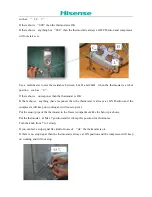
1 means power port 2 means defrost port 3 means common port 4 means compressor port
1
、
1-3 is the timer coil running connect wire port.
2
、
3-4 is compressor running connect wire port
3
、
3-2 is defrost heater working connect wire port
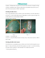
Checking method as following picture:
As picture, set the timer to the compressor running, use the multimeter measure the foots of 3 and 4,
if the value of resistance is 0000, it means normal.
Because there is capacitance resistance in the timer’s internal circuit, so when you use the multimeter
to measure the coil running port, it will can’t measure the value. If you want to measure the coil
running is normal or not, you can power on (220V) to foot 1 and 3 of timer, then put the timer near to
your ear
,
if you can hear the running sound, it means normal, if no hearing the running sound, it
means anormal.
NOTE: When measure the using the power supply to measure please pay attention to the timer’s
working voltage.
Picture 1 Picture 2
Summary of Contents for RD-31WC4S series
Page 4: ...Parts Description Circuit diagrams and Basic parameters ...
Page 18: ...Water Dispenser ...
Page 19: ......

