ENGINE
- 179 -
3
、
INSTALL
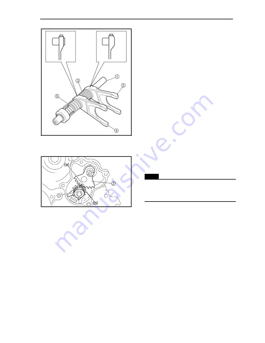
1). Assembling the shift fork
• guide bar
①
• shift fork 2
②
• long spring
③
• shift fork 1
④
• short spring
⑤
2). Installing the shift levers
• shift lever 2 assembly
①
(14Nm)
• shift lever 1
②
NOTE
:
When installing the shift lever 1, align the
punch mark (a) on the shift lever 1 with the
punch marks (b) on the shift lever 2.
3). Assembling the oil pump
• inner rotor
• outer rotor
• oil pump shaft
(with the recommended lubricant)
Summary of Contents for HS800UTV 2014
Page 91: ...SPECIFICATIONS 79 HYDROGRAPHIC CHART Hydrographic chart Pressure ...
Page 92: ...SPECIFICATIONS 80 LUBRICATION OIL WAY LUBRICATION OIL WAY Pressure splashing oil ...
Page 289: ...CHASSIS 277 Fuel tank cap Remove the fuel tank cap by turning it counterclockwise ...
Page 353: ......
Page 354: ......
Page 355: ......
Page 356: ......
Page 357: ......
Page 358: ......
Page 359: ......
Page 360: ......
Page 361: ......


