ELECTRICAL COMPONENTS
- 289 -
TURNS
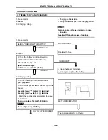
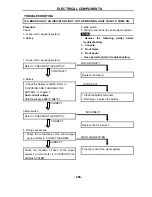
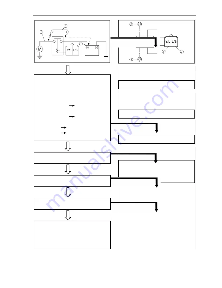
4. Starter relay
• Remove the starter relay from the wire
harness.
• Connect the pocket tester (
Ω
× 1) and the
battery (12 V) to the starter relay terminals.
Battery (+) terminal
Yellow/Blue
terminal
①
Battery (–) terminal
Blue/Black terminal
②
Tester (+) lead
Red terminal
③
Tester (–) lead
Black terminal
④
• Check the starter relay for continuity.
CONTINUITY
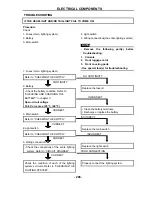
5. Main switch Refer to “CHECKING THE
SWITCH”.
CORRECT
6. Gear position switch Refer to “CHECKING
THE SWITCH”.
CORRECT
7. Brake light switch Refer to “CHECKING
THE SWITCH”.
CORRECT
8. Diode 1
• Remove the diode from the coupler
• Connect the pocket tester (
Ω
× 1) to the
diode terminals as shown.
• Check the diode for continuity as follows
NO CONTINUITY
Replace the starter relay.
INCORRECT
Replace the main switch.
INCORRECT
Replace the gear position switch.
INCORRECT
Replace the brake light switch.
Removed from the coupling diodes
Small diode Tester connection terminals, As
shown in the figure
Check the diode continuity
Summary of Contents for HS800UTV 2014
Page 91: ...SPECIFICATIONS 79 HYDROGRAPHIC CHART Hydrographic chart Pressure ...
Page 92: ...SPECIFICATIONS 80 LUBRICATION OIL WAY LUBRICATION OIL WAY Pressure splashing oil ...
Page 289: ...CHASSIS 277 Fuel tank cap Remove the fuel tank cap by turning it counterclockwise ...
Page 353: ......
Page 354: ......
Page 355: ......
Page 356: ......
Page 357: ......
Page 358: ......
Page 359: ......
Page 360: ......
Page 361: ......


