GENERAL INFORMATION
- 25 -
Clean all parts with cleaning solvent when removing them.
CAUTION
Do not direct high-pressure water at steering
bearings, fuel hoses, wheel bearings,
suspension and electrical components.
Water may force grease out of the bearings
and possibly damage the seals
14. If special tools are required, have them available before starting the procedure. When special
tools are required, they are described at the beginning of the procedure.
15. Make diagrams of similar-appearing parts. For instance, crankcase bolts are often not the same
lengths. Do not rely on memory alone. Carefully laid out parts can become disturbed, making it
difficult to reassemble the comports correctly.
16. Make sure all shims and washers are reinstalled in the same location and position.
17. Whenever rotating parts contact a stationary part, look for a shim or washer.
18. Use new gaskets if there is any doubt about the condition of old ones.
19. If using self-locking fasteners, replace them with new ones. Do not install standard fasteners in
place of self-locking ones.
20. Use grease to hold small parts in place if they tend to fall out during assembly. Do not apply
grease to electrical or brake components.
Removing Frozen Fasteners
If a fastener cannot be removed, several methods
may be used to loosen it. First, apply a penetrating
fluid. Apply it liberally and let it penetrate for 10-15
minutes. Rap the fastener several times with a small
hammer. Do not hit it hard enough to cause damage.
Reapply the penetrating fluid if necessary.
For frozen screws, apply penetrating fluid as
described, the insert a screwdriver in the slot and rap
the top of the screwdriver with a hammer. This loosens
the rust so the screw can be removed in the normal
way. If the screw head is too damaged to use this
method, grip the head with locking pliers and twist the
screw out.
Avoid applying heat unless specifically instructed.
Heat may melt, warp or remove the temper from parts.
Removing Broken Fasteners
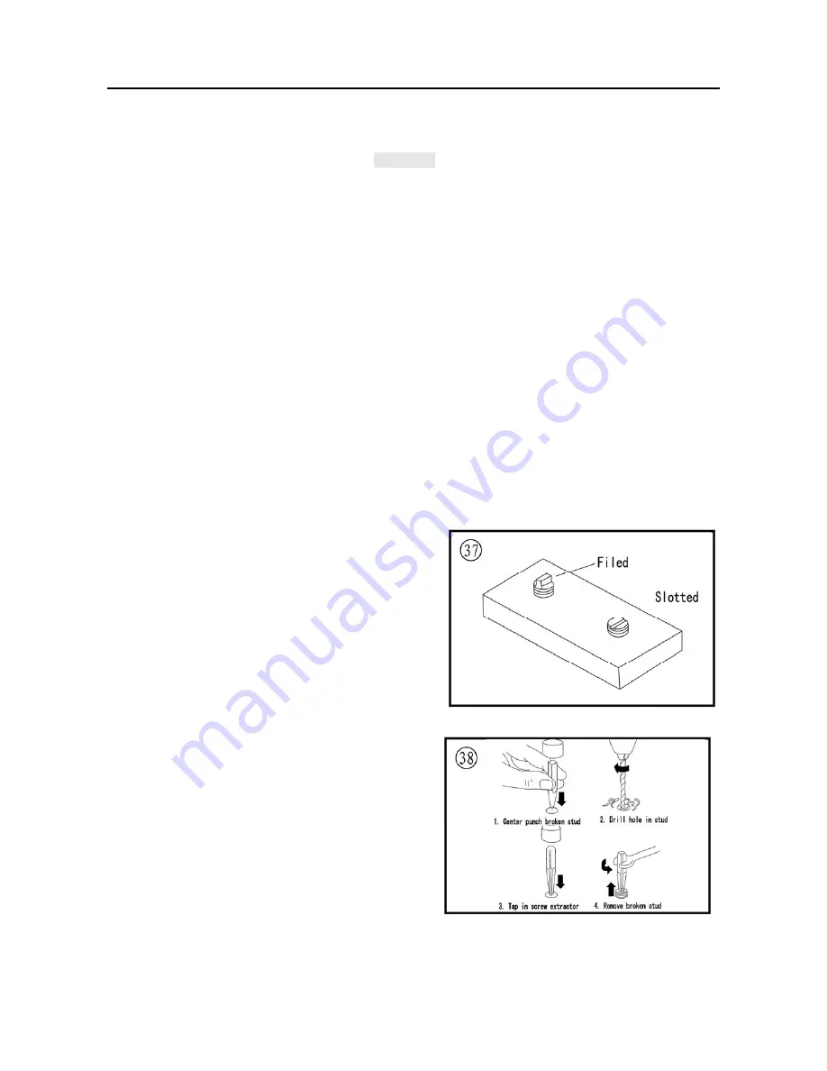
If the head breaks off a screw or bolt, several methods are available for removing the remaining
Summary of Contents for HS800UTV 2014
Page 91: ...SPECIFICATIONS 79 HYDROGRAPHIC CHART Hydrographic chart Pressure ...
Page 92: ...SPECIFICATIONS 80 LUBRICATION OIL WAY LUBRICATION OIL WAY Pressure splashing oil ...
Page 289: ...CHASSIS 277 Fuel tank cap Remove the fuel tank cap by turning it counterclockwise ...
Page 353: ......
Page 354: ......
Page 355: ......
Page 356: ......
Page 357: ......
Page 358: ......
Page 359: ......
Page 360: ......
Page 361: ......


