-270-
ENGINE MANAGEMENT SYSTEM
- 270 -
3
.
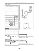
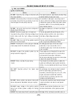
Throttle Body Removal
Disconnect negative terminal of the battery
Disconnect electric lead wire of throttle position sensor coupler, stepper motor coupler and
MAP/MAT sensor coupler ( if this sensor is mounted on the throttle body)
Disconnect accelerator cable from throttle body
Remove air cleaner outlet hose and throttle body outlet hose
4
.
Cleaning Procedure
If there is cover on the bottom, it may be removed and cleaned using carburetor cleaner (3M
make recommended). Once the throttle body cover is removed, spray the throttle-body cleaner
inside the shipping air passage, and use the brushes to gently dislodge the dirt, gum and
varnish that are present. Do not let the bye pass holes be blocked by dirt or foreign particles.
5
.
Throttle Body Installation
Reverse the procedure for installation noting the following:
Adjust accelerator cable play
Check to ensure that all removed parts are back in place.Reinstall any necessary part which
have not been reinstalled
6
.
Precautions
Do not submerge TPS in any cleaning fluid.
Always open the throttle valve using the throttle cable or lever.
Do not hold the valve at opening position by inserting tools or any sticks into the bore. The
valve may be warped and the bore may be scratched. This type of damage may keep the
throttle from opening easily or fully closing.
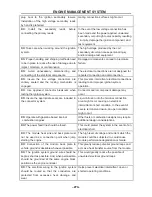
Engine Coolant Temperature Sensor
1
.
Description and Working Principle
This sensor is used in water cooled engines. It provides a resistance that varies as a function of
temperature within prescribed tolerance limits. The sensor has a negative temperature
coefficient of resistance. This is a non-serviceable part.
2
.
Installation Requirements
Dynamic Torque Requirement: The sensor shall be hand into the application and then
driven by a driver with a maximum no load speed of 400 rpm or installed to the desired
torque by a hand torque wrench (5/8” hex). The recommended installation torque is:
Minimum: 20 N·m
Maximum: 25 N·m
Static Torque Requirement: The torque required to remove the sensor from the mating hole
shall be within 200% of the installation torque mentioned above.
3
.
Sample Cleaning
When necessary the samples may be cleaned in isopropyl alcohol for one minute with
mating connectors in place and then air-dried
ENGINE MANAGEMENT SYSTEM
- 271 -
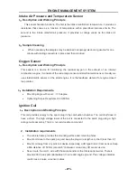
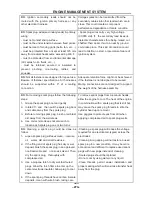
Intake Air Pressure and Temperature Sensor
1
.
Description and Working Principle
This sensor has two functions. The first is the intake manifold air temperature, it provides a
resistance that varies as a function of temperature within prescribed tolerance limits. The
second is the intake manifold air pressure; it provides a voltage varies as the intake air
pressure.
2
.
Sample Cleaning
When necessary the samples may be cleaned in isopropyl alcohol or gasoline for one
minute with mating connectors in place and then air-dried
Oxygen Sensor
1
.
Description and Working Principle
This sensor is a device for monitoring the residual oxygen in the exhaust of an internal
combustion engine. It consists of the wide range sensor and stoichiometric sensor. Usually we
use stoichiometric sensor on the small engine. It is the feedback element for engine closed
loop control.
2
.
Installation Requirements
Mounting Angle with Level:
≥
10 degree
Tightening Torque Requirement: 40-60 Nm
Ignition Coil
1
.
Description and Working Principle
This coil provides energy to the spark plug in the combustion chamber. The coil itself doesn’t
have a driver. The high voltage tower of the coil is connected to the spark plug using a high
voltage cable assembly. This is a non-serviceable component.
2
.
Installation requirements
The vehicle frame provides the mounting surface and mounting holes.
Mount coil close to the spark plug and keep the plug wire length very short (less than 6 “).
Mount coil away from any pick coil device. Especially, a VR type Crank / Cam sensor. Keep
a Min distance of 150 mm (around 6”) between coil and any VR sensor device.
Never route the coil C- wire with the same bundle as the Crank sensor wires. There is
around 200 V peak potential between C- wire and engine ground. This voltage potential
could cause a noise on sensor cables.
Summary of Contents for HS200UTV
Page 3: ......
Page 15: ......
Page 94: ... 79 SPECIFICATIONS 79 HYDROGRAPHIC CHART Hydrographic chart Pressure ...
Page 95: ... 80 SPECIFICATIONS 80 LUBRICATION OIL WAY LUBRICATION OIL WAY Pressure splashing oil ...
Page 248: ... 233 CHASSIS 233 Fuel tank cap Remove the fuel tank cap by turning it counterclockwise ...
Page 263: ... 248 ...
Page 304: ... 289 ...
Page 305: ... 290 ...
Page 306: ... 291 ...
Page 307: ... 292 ...
Page 308: ... 293 ...
Page 309: ... 294 ...
Page 310: ... 295 ...
Page 311: ... 296 ...

