background image

-70-


  SPECIFICATIONS                           


- 70- 


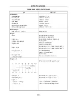
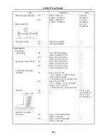
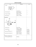
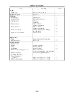
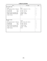
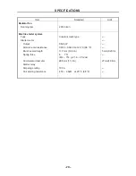
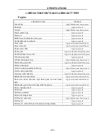
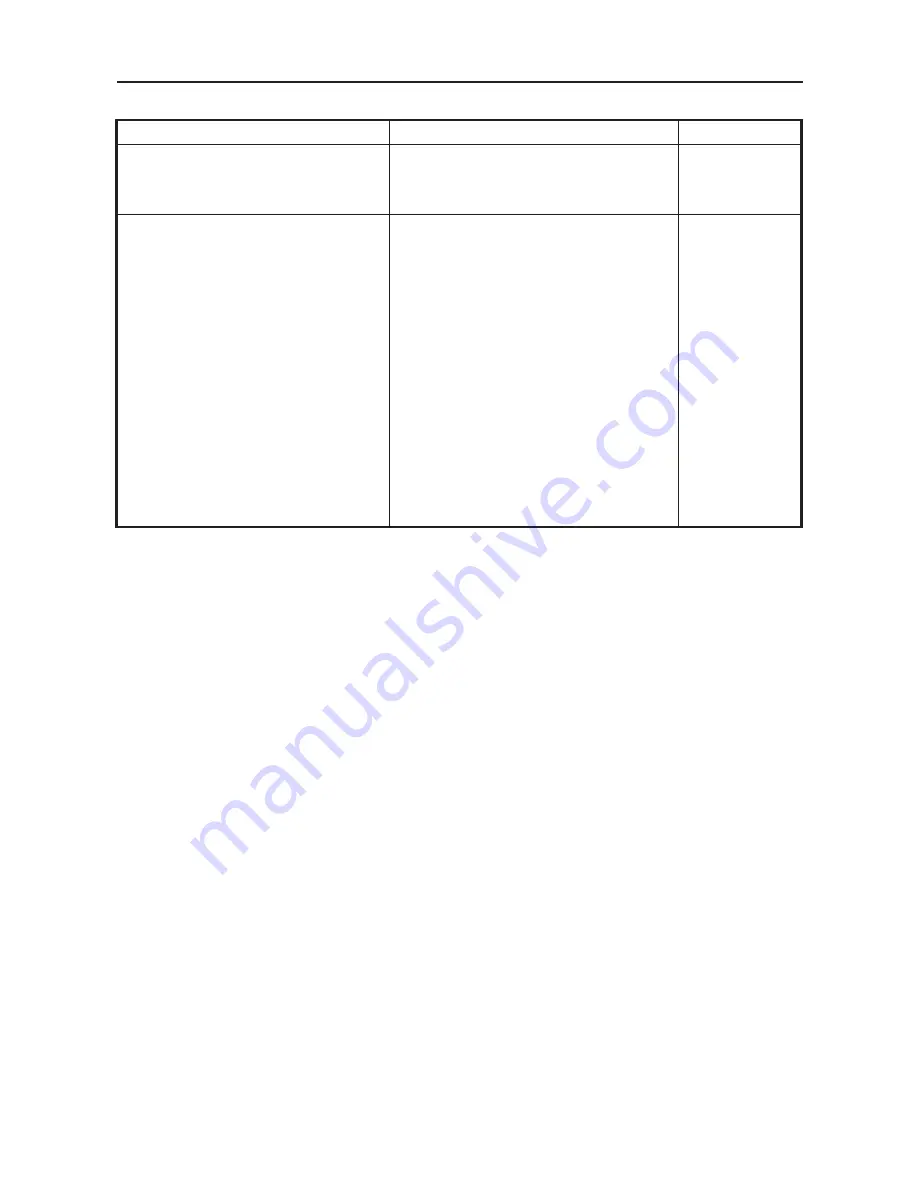
Item Standard 

Limit 

Radiator fan


Running rpm      


2,950 r/min 


Electric starter system 

Type 


Starter motor 


Output  
Armature coil resistance


Brush overall length 
Spring force   
 
Commutator diameter 


Starter relay     
Amperage rating     
Coil winding resistance


Constant mesh type     


0.52 kW 
0.039 ~ 0.044 

 at 20 °C (68 °F) 

11.7 mm (0.46 in)


 7N


(612 ~ 714 g, 21.6 ~ 25.2 oz)


28.5mm (1.12 in) 


180 A 
4.18 ~ 4.62

at 20 °C (68 °F)


----


---- 
---- 
---- 
5 mm(0.20 in) 
---- 
 
27 mm(1.06 in) 
 
---- 
----


  SPECIFICATIONS                           


- 71- 

TIGHTENING TORQUES 

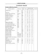
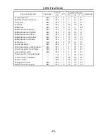
Engine tightening torques     

Part to be tightened


Part name

Thread

size


Q’ty

Tightening torque


Remarks

Nm m · kg


ft · lb


Cylinder head    
 
Spark plug    
Cylinder head (exhaust pipe)     
Cylinder head cover   
Tappet cover (exhaust)   
Tappet cover (intake)   
Oil gallery bolt   
Camshaft end cap   
Cylinder  
 
Balancer driven gear 
Timing chain tensioner   
Timing chain tensioner cap       
Timing chain guide (intake side) 
Camshaft sprocket 
Rocker arm shaft stopper   
Valve adjusting locknut 
Engine oil drain bolt 
Oil filter cartridge union bolt 
Oil filter cartridge   
Oil pipe assembly   
Oil delivery pipe 1   
Oil delivery pipe 2   
Oil delivery pipe 3   
Oil delivery pipe 2 and oil delivery 
pipe 3     
Relief valve assembly plate 
Oil strainer   
Oil pump assembly   
Intake manifold   
Intake manifold screw clamp   
 

Bolt 
Bolt  
— 
Stud bolt 
Bolt 
— 
Bolt 
— 
Bolt 
Bolt 
Bolt 
Nut  
Bolt  
Bolt  
Bolt 
Bolt  
Bolt 
— 
— 
— 
— 
Bolt  
Union Bolt
Union Bolt
Union Bolt
Union bolt 
 
Bolt  
Bolt  
Bolt  
Bolt  
— 

M6 
M9 
M12  
M8 
M6 
M32  
M6  
M6    
M6 
M6 
M10  
M18  
M6  
M6  
M6  
M7  
M6  
M6  
M14  
M20  
M20 
M6  
M8  
M14  
M10 
M14 
 
M6 
M6 
M6 
M6 
M5 


6  


17   

4  

1  

4  
1  
2  
1  
2  
2  
2  
5  


10 
38 
18 
15 
10 
12 
10 

10 
10 
42 
110 
10 
7  
8  
20 
10 
14 
30 
63 
17 

18 
35 
20 
35 
 
10 
10 
10 
10 

1.0 
3.8 
1.8 
1.5 
1.0 
1.2 
1.0 
0.7 
1.0 
1.0 
4.2  
11.0  
1.0  
0.7  
0.8  
2.0  
1.0  
1.4  
3.0 
6.3 
1.7 
0.7 
1.8 
3.5 
2.0 
3.5 
 
1.0 
1.0 
1.0 
1.0 
0.3 

7.2 
27 
13 
11 
7.2 
8.7 
7.2 
5.1 
7.2 
7.2 
30 
80 
7.2 
5.1 
5.8 
14 
7.2 
10 
22 
4.6 
12 
5.1 
13 
25 
14 
25 
 
7.2 
7.2 
7.2 
7.2 
2.1 


Summary of Contents for HS200UTV

Page 1: ...ting without permission READ THIS MANUAL CAREFULLY For questions regarding this UTV please contact HISUN at 972 446 0760 hisunmotors com Rev 06031601 No one under the age of 12 should operate this vehicle Provincial Municipal governments have different regulations pertaining to owning and operating an off road vehicle learn the regulations in your area STRIKE 250 SERVICE MANUAL TM GRAB SOME SUN ...

Page 2: ...UTV Please read the handbook through and fully understand it otherwise any improper repairing and amounting would bring you problems and accident may occur in your use Proper use and maintenance can guarantee UTV being driven safely reduce its malfunction and help the vehicle remain its best performance The standards performances and specifications mentioned in interpretation are based on the samp...

Page 3: ......

Page 4: ...fely 4 Cleaning parts 5 Warning labels 5 SERIAL NUMBERS 6 FASTENERS 6 Torque specifications 6 Self locking fasteners 6 Washers 6 Cotter pins 7 Snap rings and E clips 7 SHOP SUPPLIES 8 Lubricants and Fluids 8 Engine oils 8 Greases 8 Brake fluid 9 Coolant 9 Cleaners Degreasers and solvents 9 Gasket sealant 9 Gasket remover 10 Thread locking compound 10 BASIC TOOLS 10 Screwdrivers 11 ...

Page 5: ...Feeler gauge 16 Calipers 17 Micrometers 17 Adjustment 18 Care 19 Metric micrometer 19 Standard inch micrometer 20 Telescoping and small bore gauges 21 Dial Indicator 21 Compression gauge 22 Multimeter 22 Cltp on ammeter 22 Magneto puller 23 ELECTRICAL SYSTEM FUNDAMENTALS 23 Voltage 23 Resistance 23 Amperage 23 BASIC SERVICE METHODS 24 Removing frozen fasteners 25 Removing broken fasteners 25 Repai...

Page 6: ...d engine 33 ENGINE WILL NOT START 34 Identifying the problem 34 Spark test 35 The starter cannot work repeatedly or can only work slowly 36 POOR ENGINE PERFORMANCE 36 The engine starts slowly or difficultly 36 Engine backfires cuts out or misfires during acceleration 36 The engine is not idling or cannot idle stably 37 Poor fuel mileage 37 Engine will not idle or idles roughly 37 Low engine power ...

Page 7: ...44 HIGH OIL CONSUMPTION OR EXCESSIVE 44 Exhaust smoke 44 Low oil pressure 44 High oil pressure 44 No oil pressure 44 Oil level too low 44 Oil contamination 45 CYLINDER LEAK DOWN TEST 45 ELECTRICAL TESTING 47 Preliminary checks and precautions 47 Intermittent problems 48 Electrical component replacement 49 Test equipment 49 Ammeter 49 Self powered test light 49 Ohmmeter 50 Jumper wire 50 TEST PROCE...

Page 8: ...liper 55 Leaking master cylinder 56 CHAPTER 2 SPECIFICATIONS HOW TO USE CONVERSION TABLE OF UNIT 57 How to use conversion table 57 Definition of unit 57 GEBERAR SPECIFICATIONS 58 ENGINE SPECIFICATIONS 61 CHASSIS SPECIFICATIONS 67 ELECTRICAL SPECIFICATIONS 69 TIGHTENING TORQUES 71 Engine tightening torques 71 Chassis tightening torques 74 GENERAL TIGHTENING TORQUE SPECIFICATIONS 76 LUBRICATION PION...

Page 9: ...warning light 97 Checking the v belt 98 Cleaning the spark arrester 99 Adjusting the brake pedal 101 Checking the brake fluid level 101 Checking the front brake pads 102 Checking the rear brake pads 102 Checking the brake hoses and brake pipes 103 Bleeding the hydraulic brake system 103 Adjusting the select lever shift rod 105 Checking the steering system 106 Adjusting the toe in 107 Adjusting the...

Page 10: ...130 CYLINDER AND PISTON 138 ENGINE LEFT CRANKCASE COVER AND A C MAGNETO 142 STARTER MOTOR AND WATER PUMP 146 RIGHT CRANKCASE COVER AND OIL FILTER 148 PRIMARY AND SECONDARY SHEAVES 150 CRANKCASE AND OIL PUMP 154 BALANCE SHAFT 156 SHIFT AND CONTROL MECHANISM 161 GEARCASE TRANSMISSION 163 CHAPTER 5 CHASSIS MALFUNCTION INSPECTION 167 PANEL AND CARGO BED Front panel 169 Side cover 171 Side cover parts ...

Page 11: ...ont Suspension 214 Rear swing arm 220 COOLING SYSTEM 225 Water radiator 225 SEAT 229 FUEL TANK 232 CHAPTER 6 ELECTRICAL COMPONENTS ELECTRICAL SYSTEM MALFUNCTION INSPECTION 234 ELECTRICAL 235 ELECTRICALCOMPONENTS 235 Checking the switch 237 Checking the switch continuity 238 Checking the bulbs and bulb sockets 239 IGNITION SYSTEM 239 Circuit diagram 239 Troubleshooting 240 ELECTRIC STARTING SYSTEM ...

Page 12: ...ING SYSTEM 259 Circuit diagram 259 Troubleshooting 260 CHAPTER 7 ENGINE MANAGEMENT SYSTEM INTRODUCTION Ems engine management system 262 Typical components of EMS 262 Layout of EMS components 263 COMPONENTS OF EMS Electronic control unit 264 Multec 3 5 injectors 265 Throttle body assembly with stepper motor 268 Engine coolant temperature sensor 270 Intake air pressure and temperature sensor 271 Oxy...

Page 13: ...OR MEDIUM AND HIGH SPEED PERFORMANCE 285 Poor medium and high speed performance 285 FAULTY GEAR SHIFTING 285 Shift lever does not move 285 Jumps out of gear 285 ENGING OVERHEATING 286 Overheating 286 FAULTY BRAKE 286 Poor braking effect 286 SHOCK ABSORBER MALFUNCTION 287 Loss of damping function 287 UNSTABLE HANDLING 287 Unstable handling 287 LIGHTING SYSTEM 287 Head light is out of work 287 Bulb ...

Page 14: ...9 HS250UTV HS200UTV WIRING EFI DIAGRAM 290 IGNITION SYSTEM CIRCUIT DIAGRAM 291 ELECTRIC STARTING SYSTEM CIRCUIT DIAGRAM 292 CHARGING SYSTEM CIRCUIT DIAGRAM 293 LIGHTING SYSTEM CIRCUIT DIAGRAM 294 SIGNALING SYSTEM CIRCUIT DIAGRAM 295 COOLING SYSTEM CIRCUIT DIAGRAM 296 ...

Page 15: ......

Page 16: ... the first time WARNINGS CAUTIONS AND NOTES The terms WARNING CAUTION and NOTE have specific meaning in this manual WARNING emphasizes areas where injury or even death could result from negligence Mechanical damage may also occur WARNINGS are to be taken seriously CAUTION emphasizes areas where equipment damage could result Disregarding a CAUTION could cause permanent mechanical damage though inju...

Page 17: ...ght shoulder protection plate 14 Fuel tank cap 15 Right Door Comp 16 Front shock absorber 17 Headlights 18 Front turning lights 19 Steering wheel 20 Low high beam light 21 Lamp switch assy 22 Speedmeter 23 DC socket 24 Emergency lamp switch 25 Winch control switch 26 passenger handrail 27 Driver seat 28 Brake pedal 29 Drive select lever 30 Accelerator pedal 31 Turning lights switch 32 Passenger se...

Page 18: ... 3 GENERAL INFORMATION 3 IDENTIFICATION CODE Frame No Frame No is carved on the right side of front main frame Engine No Engine NO Is carved on the right side of the engine Figure ...

Page 19: ...d air and chemicals 11 Wear the correct clothing for the job Tie up or cover long hair so it does not get caught in moving equipment 12 Do not carry sharp tools in clothing pockets 13 Always have an approved fire extinguisher available Make sure it is rated for gasoline Class B and electrical Class C fires 14 Do not use compressed air to clean clothes the UTV or the work area Debris may be blown i...

Page 20: ...ical cleaners and solvents are available for shop use Most are poisonous and extremely flammable To prevent chemical exposure vapor buildup fire and serious injury observe each product warning label and note the following 1 Read and observe the entire product label before using any chemical Always know what type of chemical is being used and whether it is poisonous and or flammable 2 Do not use mo...

Page 21: ...e various subassemblies are not installed and tightened correctly Fasteners that are improperly installed or work loose can cause extensive damage it is essential to use an accurate torque wrench as described in this chapter Self Locking Fasteners Several types of bolts Screws and nuts incorporate a system that creates interference between the two fasteners Interference is achieved in various ways...

Page 22: ... secure parts within housing bores In some applications in addition to securing the component s snap rings of varying thicknesses also determine endplay These are usually called selective snap rings The two basic types of snap rings are machined and stamped snap rings Machined snap rings Figure 2 can be installed in either direction Because both faces have sharp edges Stamped snap rings Figure 3 a...

Page 23: ... oil satisfies The classifications are MA high friction applications and MB low frication applications NOTE Refer to Engine Oil and Filter in Chapter Three for further information on API SAE classifications Always use an oil with a classification recommended by the manufacturer Using an oil with a different classification can cause engine damage Viscosity is an indication of the oil s thickness Th...

Page 24: ...e most common from of antifreeze Check the UTV Manufacturer s recommendations when selecting antifreeze Most require one specifically designed for aluminum engines There types of antifreeze have additives that inhibit corrosion Only mix antifreeze with distilled water Impurities in tap water may damage internal cooling system passages Cleaners Degreasers and Solvents Many chemicals are available t...

Page 25: ...be carried out with basic hand tools and test equipment familiar to the home mechanic Always use the correct tools for the job Keep tools organized and clean Store them in a tool chest with related tools organized together Quality tools are essential The best are constructed of high strength alloy steel These tools are light easy to use and resistant to wear Their working surface is devoid of shar...

Page 26: ... found on the driving faces or flutes of the screwdriver s tip figure 4 ACR Phillips II screwdrivers were designed as part of a manufacturing drive system to be used with ACR Phillips II screws but they work of tool companies offer ACR Phillips II screwdrivers in different Tip size and interchangeable bits to fit screwdriver bit holders NOTE Another way to prevent cam out and to increase the grip ...

Page 27: ... contact the fastener at only two points which makes them more subject to slipping off the fastener Because one jaw is adjustable and may become loose this shortcoming is aggravated Make certain the solid jaw is the one transmitting the force Socket Wrenches Ratchets and Handles Sockets that attach to a ratchet handle Figure 7 are available with 6 point or 12 point openings Figure 8 and different ...

Page 28: ...maging them Impact drivers and interchangeable bits Figure 10 are available from most tool suppliers When using a socket with an impact driver Make sure the socket is designed for impact use Refer to Socket Wrenches Ratchets and handles in this section WARNING Do not use hand sockets with air or impact tools because they may shatter and cause injury Always wear eye protection when using impact or ...

Page 29: ...que adapter changes the effective lever length Figure 14 the torque reading on the wrench will not equal the actual torque applied to the fastener It is necessary to recalibrate the torque setting on the wrench to compensate for the change of lever length When using a torque adapter at a right angle to the drive head calibration is not required because the effective length has not changed To recal...

Page 30: ...otter pins Use needle nose pliers to hold or bend small objects Locking pliers Figure 16 sometimes called Vise Grips are used to hold objects very tightly They have many uses ranging from holding two parts together to gripping the end of a broken stud Use caution when using locking pliers as the sharp jaws will damage the objects they hold Snap Ring Pliers Snap ring pliers are specialized pliers w...

Page 31: ...many of the procedures described in this manual Equipment is manufactured to close tolerances and obtaining consistently accurate measurements is essential to determine which components require replacement or further service Each type of measuring instrument is designed to measure a dimension with a certain degree of accuracy and within a certain range When selecting the measuring tool make sure i...

Page 32: ...n the tool and the object being measured Never force the caliper to close around an object Close the caliper around the highest point so it can be removed with a slight drag Some calipers require calibration Always refer to the manufacturer s instructions when using a new or unfamiliar caliper To read a vernire Calipers refer to Figure 21 The fixed scale is marked in l mm increments Ten individual...

Page 33: ...r around the highest point so it can be removed with a slight drag Adjustment Before using a micrometer check its adjustment as follows 1 Clean the anvil and spindle faces 2A To check a 0 1 in or 0 25 mm micrometer a Turn the thimble until the spindle contacts the anvil If the micrometer has a ratchet stop use it to ensure that the proper amount of pressure is applied b If the adjustment is correc...

Page 34: ...to prevent corrosion Metric micrometer The standard metric micrometer Figure 24 is accurate to one one hundredth of a millimeter 0 01 mm The sleeve line is graduated in millimeter and half millimeter increments The marks on the upper half of the sleeve line equal 1 00 mm Each fifth mark above the sleeve line is identified with a number The number sequence depends on the size of the micrometer A 0 ...

Page 35: ...5 6 7 8 9 These numbers indicate 0 100 0 200 0 300 and so on The tapered end of the thimble has 25 lines marked around it Each mark equals 0 001 in One complete turn of the thimble will align its zero mark with the first mark on the sleeve or 0 025 in To read a standard inch micrometer perform the following steps and refer to Figure 27 1 Read the sleeve and find the largest number visible Each sle...

Page 36: ...e bore Do not over tighten the gauge because there is no built in release Excessive tightening can damage the bore surface and damage the tool Remove the gauge and measure the outside dimension Figure 30 Small bore gauges are typically used to measure valve guides Dial Indicator A dial indicator Figure 31 is a gauge with a dial face and needle used to measure variations in dimensions and movements...

Page 37: ...y if using a meter not recommended by the manufacturer Such requirements are noted when applicable Ohmmeter analog calibration Each time an analog ohmmeter is used or if the scale is changed the ohmmeter must be calibrated Digital ohmmeters do not require calibration 1 Make sure the meter battery is in good condition 2 Make sure the meter probes are in good condition 3 Touch the two probes togethe...

Page 38: ...ct current to operate in a battery powered system Resistance Resistance is the opposition to the flow of electricity within a circuit or component and is measured in ohms Resistance causes a reduction in available current and voltage Resistance is measured in an inactive circuit with an ohmmeter The ohmmeter sends a small amount of current into the circuit and measures how difficult it is to push ...

Page 39: ...cals off painted surfaces 6 Use penetrating oil on frozen or tight bolts Avoid using heat where possible Heat can warp melt or affect the temper of parts Heat also damages the finish of paint and plastics 7 When a part is a press fit or requires a special tool to remove the information or type of tool is identified in the text Otherwise if a part is difficult to remove or install determine the cau...

Page 40: ...fall out during assembly Do not apply grease to electrical or brake components Removing Frozen Fasteners If a fastener cannot be removed several methods may be used to loosen it First apply a penetrating fluid Apply it liberally and let it penetrate for 10 15 minutes Rap the fastener several times with a small hammer Do not hit it hard enough to cause damage Reapply the penetrating fluid if necess...

Page 41: ...l Figure 40 is available from most tool suppliers This tool makes the removal and installation of studs easier If one is not available thread two must onto the stud and tighten them against each other Remove the stud by turning the lower nut Figure 41 1 Measure the height of the stud above the surface 2 Thread the stud removal tool onto the stud and tighten it or thread two nuts onto the stud 3 Re...

Page 42: ...ections as a guideline NOTE Unless otherwise specified install bearings with the manufacturer s mark or number facing outward Removal While bearing are normally removed only when damaged there may be times when it is necessary to remove a bearing that is in good condition However improper bearing removal will damage the bearing and possibly the shaft or case Note the following when removing bearin...

Page 43: ... shaft and into the housing at the same time a tight fit is required for both outer and inner bearing races In this situation install a spacer underneath the driver tool so that pressure is applied evenly across both races See Figure 48 If the outer race is not supported as shown the balls will push against the outer bearing race and damage it Interference fit 1 Follow this procedure when installi...

Page 44: ...izzle and evaporate immediately the temperature is correct Heat only one housing at a time CAUTION Do not heat the housing with a propane or acetylene torch Never bring a flame into contact with the bearing or housing The direct heat will destroy the case hardening of the bearing and will likely warp the housing b Remove the housing from the oven or hot plate and hold onto the housing with welding...

Page 45: ...ice Storage Area Selection When selecting a storage area consider the following 1 The storage area must be dry A heated area is best but not necessary It should be insulated to minimize extreme temperature variations 2 If the building has large window areas mask them to keep sunlight off the UTV 3 Avoid buildings in industrial areas where corrosive emissions may be present Avoid areas close to sal...

Page 46: ... the intake and exhaust openings 2 Service the air filter as described in Chapter Three 3 Inspect the cooling system Check the drain plug and hose connections for leaks 4 Refill the fuel tank Turn the fuel shutoff valve on and check for fuel leaks 5 Make sure the brakes clutch throttle and engine stop switch work properly before operating the UTV Evaluate the service intervals to determine which a...

Page 47: ...park at the right time If one basic requirement is missing the engine will not run STARTING THE ENGINE When experiencing engine starting troubles it is easy to work out of sequence and forget basic starting procedures The following sections describe the recommended starting procedures Several special faults and countermeasures of EFI engine system 1 Special fault Idle speed is too high at starting...

Page 48: ...hrottle idle speed step motor inside ECU need to match the volume of oil when in idle speed automatically Countermeasure When start the engine run 2 to 3 minutes in idle speed If it can t run normally in idle turn off the engine and restart it repeatedly 10 seconds later until it can run normally in idle Or switch on and off the key 5 times in a row which can reset all saved data in ECU Engine is ...

Page 49: ...e the fuel tank and make sure the fuel tank has a sufficient amount of fuel to start the engine 4 If there is sufficient fuel in the fuel tank remove the spark plug immediately after attempting to start the engine The plug s insulator should be wet indicating that fuel is reaching the engine If the plug tip is dry fuel is not reaching the engine Refer to Fuel System in this chapter If there is fue...

Page 50: ...ng correctly CAUTION After removing the direct ignition coil or spark plug cap and before removing the spark plug in Step 1 clean the area around the spark plug with compressed air Dirt that falls into the cylinder causes rapid engine wear 1 Disconnect the direct ignition coil or spark plug cap Check for the presence of water 2 Visually inspect the spark plug for damage 3 Connect a spark tester to...

Page 51: ...t hot start valve adjustment 3 The fuel tank connection hose is clogged 4 The fuel hose is clogged or the oil filter is clogged 5 The injector is clogged NOTE If a warm or hot engine will start with the choke on or if a cold engine starts and runs until the choke is turned off The pilot jet is probably plugged 6 Contaminated or stale fuel 7 Clogged air filter 8 Intake pipe air leak 9 Plugged exhau...

Page 52: ... Stably If the engine backfires when the throttle is released check the following 1 Lean throttle pilot system 2 Loose exhaust pipe to cylinder head connection 3 Faulty ignition system component 4 Check the following engine components a Broken valve springs b Stuck or leaking valves c Worn or damaged camshaft lobes d Incorrect valve timing due to incorrect camshaft installation or a mechanical fai...

Page 53: ...s the UTV and accelerate lightly If the engine speed increased according to throttle position Perform Step 4 If the engine speed did not increase Check for one or more of the following problems a Clogged air filter b Restricted fuel flow c Pinched fuel tank breather hose Figure 9 d Clogged or damaged silencer or muffler NOTE A clogged exhaust system will prevent some of the burned exhaust gasses f...

Page 54: ...he fuel system as described in this chapter Poor High Speed Performance 1 Check ignition timing If the ignition timing is correct Perform Step 2 If the timing is incorrect Perform the Peak Voltage 2 Check the fuel system as described in this chapter 3 Check the valve clearance as described Note the following a If the valve clearance as correct Perform Step 4 b If the clearance is incorrect adjust ...

Page 55: ...rts of the fuel have evaporated Depending on the condition of the fuel a no start condition can result c If there is too much fuel on the end of the spark plug go to check whether there is overflow at the air filter or the ducting damper Rich Mixture The following conditions can cause a rich air fuel mixture 1 Air pressure sensor oxygen sensor solar term door position sensor fault 2 ECU program er...

Page 56: ...ter collects As this water mixes with the oil in the crankcase sludge is produced Sludge can eventually cause engine damage as it circulates through the lubrication system and blocks off oil passages Large amounts of steam can also be caused by a cracked cylinder head or cylinder block surface that allows coolant to leak into the combustion chamber Perform a Coolant System Pressure Test Low Engine...

Page 57: ...ing properly 4 Valves leaking 5 Heavy carbon deposits in the combustion chamber 6 Dragging brake s 7 Slipping clutch The Ignition Advance Angle Is Too Large Preignition is the premature burning of fuel and is caused by hot spots in the combustion chamber Glowing deposits in the combustion chamber inadequate Cooling or an overheated spark plug can all cause preignition This is first noticed as a po...

Page 58: ...nded May also be caused by poor fuel Pinging can also be caused by an incorrect spark plug heat range or carbon buildup in the combustion chamber 2 Slapping or rattling noises at low speed or during acceleration May be caused by excessive piston to cylinder wall clearance piston slap NOTE Piston slap is easier to detect when the engine is cold and before the piston has expanded Once the engine has...

Page 59: ... pump 3 Clogged oil strainer screen 4 Clogged oil filter 5 Internal oil leakage 6 Oil relief valve stuck open 7 Incorrect type of engine oil High Oil Pressure 1 The lubrication oil pressure valve is stuck and closed 2 Clogged oil filter 3 Clogged oil gallery or metering orifices No Oil Pressure 1 Low oil level 2 The lubrication oil pressure valve is stuck and closed 3 Damaged oil pump 4 Incorrect ...

Page 60: ...ombustion chamber starts to pressurize Any piston movement will force the crankshaft to turn away from TDC and allow air to escape past an open valve seat In this procedure it will be necessary to lock the engine at TDC on its compression stroke and then perform the leak down test Follow the manufacturer s directions along with the follow the manufacturer s directions along with the following info...

Page 61: ...nder considerable force attempting to hole the tool can cause serious injury Engine damage may also occur to the crankshaft or right crankcase cover Lock the engine as described in this procedure a Turn the drive sprocket by hand and shift the transmission into top gear with the shift pedal b Mount a holding tool or equivalent onto the drive sprocket Use a wooden block and clamp to hold the holdin...

Page 62: ...ng diagrams at the end of the manual for component and connector identification Use the wiring diagrams to determine how the circuit should work by tracing the current paths from the power source through the circuit components to ground Also check any circuits that share the same fuse if used ground or switch If the other circuits work properly and the shared wiring is good the cause must be in th...

Page 63: ...art Check for wires with cracked or broken insulation NOTE An analog ohmmeter is useful when making this type of test Slight needle movements are apparent when indicating a loose connection 2 Heat This is another common problem with connectors or plugs that have loose or poor connections As these connections heat up The connection or joint expands and separates Causing an open circuit Other heat r...

Page 64: ...structed from a 12 volt light bulb with a pair of test leads carefully soldered to the bulb To check for battery voltage in a circuit attach one lead to ground and the other lead to various points along the circuit The bulb lights when battery voltage is present A voltmeter is used in the same manner as the test light to find out if battery voltage is present in any given circuit The voltmeter unl...

Page 65: ...is there is no measurable resistance in the meter needle falls between these two ends of the scale this indicates the actual resistance multiply the meter reading by the ohmmeter scale For example a meter reading of 5 multiplied by the R 100 scale is 5000 ohms of resistance CAUTION Never connect an ohmmeter to a circuit which has power applied to it Always disconnect the battery negative lead befo...

Page 66: ...med with a test or a voltmeter A voltmeter gives the best results NOTE If using a test light It does not make any difference which test lead is attached to ground 1 Attach the voltmeter negative test lead to a good ground bare metal Make sure the part used for ground is not insulated with a rubber gasket or rubber grommet 2 Attach the voltmeter positive test lead to the point to be tested 3 Turn t...

Page 67: ...nd connections Peak voltage test Peak voltage tests check the voltage output of the ignition coil and ignition pulse generator at normal cranking speed These tests make it possible to identify ignition system problems quickly and accurately Peak voltage tests require a peak voltage adapter or tester See Chapter Ten Ignition System Testing Continuity Test A continuity test is used to determine the ...

Page 68: ... next to the fuse terminal a work systematically away from the fuse terminal Watch the test light or voltmeter while progressing along the harness 4 If the test light blinks or if the needle on the voltmeter moves there is a short to ground at that point in the harness BRAKE SYSTEM The front and rear brake units are critical to riding performance and safety Inspect the front and rear brakes freque...

Page 69: ... A leaking fork seal can allow oil to contaminate the brake pads and disc 11 Worn or damaged master cylinder cups and or cylinder bore 12 Worn or damaged brake caliper piston seals 13 Contaminated master cylinder assembly 14 Contaminated brake caliper assembly 15 Brake caliper not sliding correctly on slide pins 16 Sticking master cylinder piston assembly 17 Sticking brake caliper pistons Brake Dr...

Page 70: ...ke caliper not sliding correctly on slide pins 9 Worn or damaged brake caliper seals Brake Grabs 1 Damaged brake pad pin bolt Look for steps or cracks along the pad pin bolt surface 2 Contaminated brake pads and disc 3 Incorrect wheel alignment 4 Warped brake disc 5 Loose brake disc mounting bolts 6 Brake caliper not sliding correctly on slide pins 7 Mismatched brake pads 8 Damaged wheel bearings ...

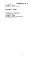
Page 71: ...eads in caliper body Leaking Master Cylinder 1 Damaged piston secondary seal 2 Damaged piston snap ring snap ring groove 3 Worn or damaged master cylinder bore 4 Loose banjo bolt washers 5 Damaged banjo bolt washers 6 Damaged banjo bolt threads in master cylinder body 7 Loose or damaged reservoir cap ...

Page 72: ...214 0 6214 3 281 1 094 0 3937 0 03937 mph mi ft yd in in Volume capacity cc cm3 cc cm3 lit liter lit liter 0 03527 0 06102 0 8799 0 2199 oz IMP liq cu in qt IMP liq gal IMP liq Others kg mm kg cm2 Centigrade 55 997 14 2234 9 5 32 Ib in psi lb in2 Fahrenheit F 2 Definition of unit Unit Read Definition Measurement mm cm Millimetre Centimetre 1 mm 10 3 Meter 1 cm 10 2 Meter Length Length kg Kilogram ...

Page 73: ... stroke Compression ratio Starting system Lubrication system HS1P65MM for HS250UTV HS1P65ML for HS200UTV single cylinder 4 stroke Water cool single cylinder 229cm3 for HS250UTV 199cm3 for HS200UTV 65 5 68mm 2 58 2 68in for HS250UTV 65 5 59mm 2 58 2 32in for HS200UTV 9 7 1 for HS250UTV 9 6 0 1 1 for HS200UTV Electric starter Pressure and splash lubrication Engine oil Final gear oil Differential gea...

Page 74: ...ion system Transmission type Operation Single speed automatic Sub transmission ratio Low High Reverse gear V belt Chain drive V belt automatic Right hand operation 1 58 0 99 36 13 29 22 3 650 34 16 29 22 2 801 36 13 2 769 Chassis Frame type Trail Toe in Steel tube frame 41mm 1 61 in 5 mm 0 20 in Tire Type Size Front Rear Pressure of front wheel Pressure of rear wheel Tubeless 22 7 10 22 10 10 49kp...

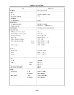
Page 75: ...inner airbag absorber 115mm 4 53 in 130mm 5 12 in Electrical Ignition system Generator system Battery type Battery capacity EFI A C magneto GSU1 9 12 V 30 0Ah Headlight type Bulb wattage quantity Headlight Front Position Lamp Front direction indicator Rear direction indicator Rear position lamp Brake lamp L gear H gear Neutral Reverse Coolant temperature Parking brake H1 12V 35W 35W 2 12V 5W 2 12V...

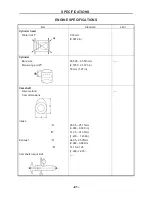
Page 76: ...0 03 mm 0 0012 in Cylinder Bore size Measuring point 65 500 65 515mm 2 5787 2 5793 in 50 mm 1 97 in Camshaft Drive method Cam dimensions Intake A B Exhaust A B Camshaft runout limit 25 05 25 15mm 0 986 0 990 in 31 25 31 35mm 1 230 1 234in 24 95 25 05mm 0 982 0 986in 31 15 31 25 1 226 1 230 ...

Page 77: ...16 0 0026in 0 08 0 15 mm 0 0031 0 0059 in Valve dimensions head diameter face width seat width margin thickness A head diameter IN EX B face width IN EX C seat width IN EX D margin thickness IN EX Stem outside diameter IN EX Guide inside diameter IN EX 33 9 34 1mm 1 3346 1 3425 in 28 4 28 6 mm 1 1181 1 1260in 3 54 mm 0 1394 in 2 83 mm 0 1114in 0 9 1 1 mm 0 0354 0 0433 in 0 9 1 1 mm 0 0354 0 0433 i...

Page 78: ...ressure installed IN EX Tilt limit IN EX Direction of winding top view IN EX Inner 39 2mm 1 54in Outer 44 9mm 1 77in Inner 39 2mm 1 54in Outer 44 9mm 1 77in Inner 33 7mm 1 33in Outer 38 4mm 1 51in Inner 33 7mm 1 33in Outer 38 4mm 1 51in Inner 75 6 87 0N 7 71 8 88 kg 17 00 19 58 lb Outer 191 4 220 2N 19 53 22 47 kg 43 06 49 54 lb Inner 75 6 87 0N 7 71 8 88 kg 17 00 19 58 lb Outer 191 4 220 2N 19 53...

Page 79: ...74 in 10 mm 0 3937 in 0 5mm 0 0197 in Intake side 15 002 15 008mm 0 5906 0 5909in 15 005 15 010 mm 0 5907 05909 in 0 15 mm 0 0059 in Piston rings Top ring Type Dimensions B T End gap installed Side clearance installed 2nd ring Type Dimensions B T End gap installed Side clearance Barrel 2 6 0 8 mm 0 1024 0 0315in 0 10 0 25mm 0 0039 0 0098 in 0 04 0 08 mm 0 0016 0 0031 in Taper 2 6 1 0mm 0 1024 0 03...

Page 80: ...6 0 15 mm 0 0024 0 0059 in Crankshaft Crank width A Runout limit C1 C2 Big end side clearance D Big end radial clearance E 54 95 55mm 2 1634 2 1654in 0 015mm 0 0006in 0 015mm 0 0006in 0 15 0 30 mm 0 0059 0 0118 in 0 003 0 015 mm 0 0001 0 0059 in 0 03 mm 0 0012 in 0 03 mm 0 0012 in 1 0 mm 0 0394 in Automatic centrifugal clutch Clutch engagement speed 2500r min ...

Page 81: ...0039 in 0 09 0 17 mm 0 0035 0 0067 in 100 Kpa 1 02 kg cm2 14 5 psi at 1 500 r min Cylinder head Water pump Type Reduction ratio Single suction centrifugal pump 22 18 1 2 Cooling system Radiator core Width Height Thickness Radiator cap opening pressure Radiator capacity including all routes Coolant reservoir Capacity From low to full level 355mm 13 98 in 195mm 7 68 in 38 mm 1 50 in 107 9 137 3 Kpa ...

Page 82: ...m 4 33 in 255 mm 10 04 in 250 mm 9 84 in 11 2 N mm 1 14 kg mm 62 71lb in 18 4N mm 1 88kg mm 103 02 lb in 0 63 mm 0 2 48 in 63 106 mm 2 48 4 17in Front wheel Type Rim size Rim material Rim runout limit radial lateral Aluminum Alloy wheel 10 5 0 AT ST12 ZL101A 1 0 mm 0 04in 1 0 mm 0 04 in Rear wheel Type Rim size Rim material Rim runout limit radial lateral Aluminum Alloy wheel 10 8 0 AT ST12 ZL101A...

Page 83: ...ide diameter Brake fluid type Dual 160 3 mm 6 30 0 12 in 8 0 mm 0 31 in 8 0 mm 0 31 in 19 0mm 0 75in 25 0mm 0 98in DOT 4 Rear disc brake Type Disc outside diameter thickness Pad thickness inner Pad thickness outer Master cylinder inside diameter Caliper cylinder inside diameter Brake fluid type Single 200 3 5 mm 7 87 0 14in 8 0 mm 0 31 in 8 0 mm 0 31 in 19 0mm 0 75in 25 0mm 0 98in DOT 4 ...

Page 84: ...tance 4 5 5 0 kΩ Oxygen sensor type 25322728 Charging system Nominal output Charging coil resistance color 14 V 23 A at 4 500 r min 0 32 0 43Ωat 20 68 F White White White Rectifier regulator Regulator type No load regulated voltage DC Capacity Withstand voltage Semi conductor Switch type 14 1 14 95 V 18 A 200 V Battery Specific gravity 1 32 Circuit breaker Type Speedmeter ECU normal open fuse Ligh...

Page 85: ... motor Output Armature coil resistance Brush overall length Spring force Commutator diameter Starter relay Amperage rating Coil winding resistance Constant mesh type 0 52 kW 0 039 0 044 Ω at 20 C 68 F 11 7 mm 0 46 in 6 7N 612 714 g 21 6 25 2 oz 28 5mm 1 12 in 180 A 4 18 4 62Ω at 20 C 68 F 5 mm 0 20 in 27 mm 1 06 in ...

Page 86: ...pipe 2 Oil delivery pipe 3 Oil delivery pipe 2 and oil delivery pipe 3 Relief valve assembly plate Oil strainer Oil pump assembly Intake manifold Intake manifold screw clamp Bolt Bolt Stud bolt Bolt Bolt Bolt Bolt Bolt Nut Bolt Bolt Bolt Bolt Bolt Bolt Union Bolt Union Bolt Union Bolt Union bolt Bolt Bolt Bolt Bolt M6 M9 M12 M8 M6 M32 M6 M6 M6 M6 M10 M18 M6 M6 M6 M7 M6 M6 M14 M20 M20 M6 M8 M14 M10...

Page 87: ...h housing assembly Bolt M6 9 10 1 0 7 2 Bearing retainer middle drive shaft Screw M8 4 29 2 9 21 Middle drive pinion gear Nut M22 1 145 14 5 105 Stake Middle drive shaft bearing housing Bolt M8 4 32 3 2 23 Middle driven pinion gear bearing Retainer Nut M60 1 110 11 0 80 Left hand threads Middle driven pinion gear bearing Housing Bolt M8 4 25 2 5 18 Primary sheave assembly Nut M16 1 120 12 0 85 Pri...

Page 88: ...0 2 0 14 Muffler bracket and frame Bolt M8 2 20 2 0 14 Muffler damper and muffler Bolt M6 1 10 1 0 7 2 Muffler damper and frame Bolt M6 1 10 1 0 7 2 Exhaust pipe Nut M8 2 14 1 4 10 Air duct assembly 1 Bolt M6 2 7 0 7 5 1 Air duct assembly 2 and left protector Bolt M6 1 7 0 7 5 1 Air duct assembly 2 and frame Bolt M6 1 7 0 7 5 1 Gear position switch Bolt M5 2 7 0 7 5 1 Thermo switch 1 cylinder head...

Page 89: ...eering Cross gimbal M8 22 2 2 16 Steering assembly and steering Cross gimbal M8 22 2 2 16 Steering assembly and frame M10 48 4 8 35 Steering shaft assembly and frame M8 21 2 1 15 Steering wheel and steering shaft assembly M12 35 3 5 25 Steering knuckle and front upper arm M12 30 3 0 22 Steering knuckle and front lower arm M12 30 3 0 22 Tie rod locknut M12 40 4 0 29 Steering knuckle and tie rod M12...

Page 90: ... 0 9 6 5 Brake rod locknut M8 17 1 7 12 Rear brake disc and brake disc Install seat M6 10 1 0 7 2 Rear brake pad holding bolt M8 17 1 7 12 Rear brake caliper and Install seat M10 40 4 0 29 Rear brake hose union bolt M10 27 2 7 19 Parking brake case and rear brake caliper M8 22 2 2 16 Parking brake lever assembly and frame M6 7 0 7 5 1 Rear brake caliper bleed screw M6 5 0 5 3 6 Upper instrument pa...

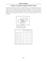
Page 91: ...tighten multi fastener assemblies in a crisscross pattern and progressive stages until the specified tightening torque is reached Unless otherwise specified tightening torque specifications require clean dry threads Components should be at room temperature A Distance between flats B Outside thread diameter A nut B bolt General tightening torques Nm m kg ft lb 10 mm 6 mm 6 0 6 4 3 12 mm 8 mm 15 1 5...

Page 92: ...cartridge O ring Apply lithium soap based grease Starter idle gear shaft Apply molybdenum disulfide grease Starter wheel gear Apply engine oil Clutch housing assembly shaft end Apply lithium soap based grease Clutch carrier assembly Apply engine oil One way clutch bearing Apply molybdenum disulfide grease Middle driven shaft splines Apply molybdenum disulfide oil Drive axle driven sprocket high wh...

Page 93: ...Joint of front brake cable Light lithium base grease Front brake lever axle and rear brake lever axle Light lithium base grease Adjusting nut and pin of front brake cable Light lithium base grease Adjusting nut and pin of rear brake cable Light lithium base grease Rear brake pedal pivot and brake pedal axle hole Light lithium base grease Throttle rotating frame shaft and end section of throttle ca...

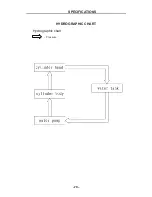
Page 94: ... 79 SPECIFICATIONS 79 HYDROGRAPHIC CHART Hydrographic chart Pressure ...

Page 95: ... 80 SPECIFICATIONS 80 LUBRICATION OIL WAY LUBRICATION OIL WAY Pressure splashing oil ...

Page 96: ...r filter element clean Replace if necessary Every20 40hours More often in wet of dusty areas Front brake Check operation fluid leakage Correct if necessary Rear brake Check operation Adjust if necessary Wheel Check balance damage Repair if necessary Front and rear suspension Check operation Correct if necessary Wheel bearing Check bearing assemblies for looseness damage Replace if necessary Steeri...

Page 97: ...re draining Engine oil strainer Clean Engine oil filter cartridge Replace Lights and switches Check operation Adjust headlight beams NOTE Recommended brake fluid DOT 4 Brake fluid replacement When disassembling the master cylinder or caliper replace the brake fluid Normally check the brake fluid level and add fluid as required On the inner parts of the master cylinder and caliper replace the oil s...

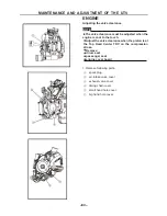
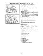
Page 98: ...hen the engine is cool to the touch Adjust the valve clearance when the piston is at the Top Dead Center TDC on the compression stroke Remove driver seat passenger seat engine cover board 1 Remove following parts spark plug air intake valve cover exhaust valve cover timing chain cover small hand hole cover big hand hole cover ...

Page 99: ...heck valve clearance Beyond the standard Adjust Valve clearance cold Intake 0 08 0 12 mm 0 0031 0 0047 in Exhaust 0 10 0 14 mm 0 0047 0 0063 in 3 calibration adjusting tools A Spin the crank when the rotoflex s scale shows 1 it is cylinder 1 s timing ...

Page 100: ...roper clearance is obtained in order to avoid adjuster rotating along fix the lock nut after finishing Fixed nut 14 Nm 1 4 m kgf 10 ft lbs Measuring clear Measure the clearance of valve with gap gauge If the gap beyond the standard value repeat the above steps until the correct gap 5 Install all removed parts According to remove the reverse order for installation big hand hole cover small hand hol...

Page 101: ...he pole clearance by thickness gauge It is qualified if the pole clearance is between 0 8 to 0 9mm Otherwise it should be adjusted Wear damage Replace insulator Abnormal color Replace Normal color is a medium to light tan color 5 Clean the spark plug with a spark plug cleaner or wire brush 6 Install spark plug 17 5 Nm 1 75 m kgf 12 7 ft lbs Then hook up the spark plug cap NOTE Before installing a ...

Page 102: ...chanism name 4 Check Engine tachometer a worm up the engine at specified speed Engine speed 1 400 1 500 r min b Visually check the stationary pointer to verify it is within the required firing range indicated on the flywheel Incorrect firing range Check the pulser coil assembly c Install the timing plug 5 Install Engine manual starting mechanism 7 Nm 0 7 m kg 5 1 ft lb 6 Install manual starting me...

Page 103: ...e highest data on the compression pressure meter Above the maximum pressure Check the cylinder head valve surfaces and piston crown for carbon deposits Below the minimum pressure Check the accumulation carbon in the firebox of the cylinder head and accumulation carbon on the piston head Refer to the table below Compression pressure with oil introduced into cylinder Reading Diagnosis Higher than wi...

Page 104: ... should be between the engine oil mirror maximum and minimum marks Oil level low Add oil to the proper level Recommended oil Follow the left chart NOTE Recommended oil classification API Service SE SF SG type or equivalent e g SF SE CC SF SE SD etc NOTE Do not allow foreign material to enter the crankcase 3 Stop the engine and check the oil level again NOTE Wait a few minutes until the oil settles...

Page 105: ...ut drain the oil Lubricate the O ring of the new oil filter cartridge with a thin coat of lithium soap based grease Tighten the new oil filter cartridge to specification with an oil filter wrench Oil filter cartridge 17 Nm 1 7 m kg 5 Install oil gauge oil draining blind nut 6 conditions Change for new oil filter before impouring oil to crankcase and make sure it is in good working condition before...

Page 106: ...ENT OF THE UTV 91 7 Install engine oil filler plug 8 Worm up the engine for a few minutes and then stop the engine 9 Check engine for engine oil leaks refer to Chapter 4 check the level of engine oil 10 Check engine oil pressure ...

Page 107: ...ement assembly air filter element cap air filter element NOTE Never operate the engine with the air filter element removed This will allow unfiltered air to enter causing rapid wear and possible engine damage Additionally operation without the filter element will affect carburetor tuning with subsequent poor performance and possible engine overheating 2 Check air filter element Damaged Replace 3 C...

Page 108: ...foam material c Squeeze out the excess oil NOTE The element should be wet but not dripping 4 Install air filter element air filter case cover NOTE To prevent air leaks make sure that the sealing surface of the element matches the sealing surface of the case CHECKING THE COOLANT LEVEL 1 Place the vehicle on a level surface 2 Remove front faceplate 3 Check start the engine warm it up for several min...

Page 109: ...nect coolant reservoir hose coolant reservoir cap Adding water instead of coolant lowers the antifreeze content of the coolant If water is used instead of coolant check and if necessary correct the antifreeze concentration of the coolant Use only distilled water However soft water may be used if distilled water is not available 2 Drain coolant from the coolant reservoir 3 Connect coolant reservoir...

Page 110: ... or a towel over the radiator cap and slowly turn the radiator cap counterclockwise toward the detent to allow any residual pressure to escape When the hissing sound has stopped turn the radiator cap counterclockwise while pressing down on it and then remove it 6 Drain coolant 7 Disconnect coolant outlet hose water pump inlet hose 8 Drain coolant 9 Check copper washer coolant drain bolt Damage Rep...

Page 111: ...lashes in your eyes thoroughly wash them with water and consult a doctor If coolant splashes on your clothes quickly wash it away with water and then with soap and water If coolant is swallowed induce vomiting and get immediate medical attention If coolant comes into contact with painted surfaces immediately wash them with water Do not mix different types of antifreeze Recommended antifreeze High ...

Page 112: ...illed water is not available 14 Install air bleed bolt 9 Nm 0 9 m kg 6 5 ft lb radiator cap Fill coolant reservoir Install coolant reservoir cap Start the engine warm it up for several minutes and then turn it off Check coolant level Refer to THE COOLANT in chapter 4 NOTE Before checking the coolant level wait a few minutes until the coolant has settled Close the hood Install driver seat Refer to ...

Page 113: ... If the sixth segment is light the cooling system would be examined because the temperature of water is too high CHECKING THE V BELT 1 Remove driver seat passenger seat engine cover board fuel tank drive belt cover Check a V belt Cracks wear scaling chipping Replace Oil grease Check primary sheave and secondary sheave b V belt width Out of specification Replace Coolant temperature warning light ch...

Page 114: ...y sheave and secondary sheave Install the V belt NOTE Install the V belt so that its arrow faces the direction shown in the illustration Remove the bolts 2 Install drive belt cover driver seat CLEANING THE SPARK ARRESTER 1 Clean Tap the tailpipe lightly with a soft face hammer or suitable tool then use a wire brush to remove any carbon deposits from the spark arrester portion of the tailpipe and t...

Page 115: ...ailpipe into the muffler and align the bolt holes Insert the bolt 1 and tighten it Start the engine and rev it up approximately twenty times while momentarily creating exhaust system back pressure by blocking the end of the muffler with a shop towel Stop the engine and allow the exhaust pipe to cool ADJUSTING THE BRAKE PEDAL 1 Check brake pedal free play a Out of specification adjust NOTE The end ...

Page 116: ...hen checking the brake fluid level make sure that the top of the brake fluid reservoir top is horizontal 2 Lift the hood up 3 Check brake fluid level Fluid level is under MIN line Fill up NOTE Brake fluid may erode painted surfaces or plastic parts Always clean up spilled fluid immediately WARNING Use only the designed quality brake fluid otherwise the rubber seals may deteriorate causing leakage ...

Page 117: ...ke pads Wear indicator groove a almost disappeared Replace the brake pads as a set Refer to FRONT AND REAR BRAKES in chapter 5 Brake pad wear limit a 1 5 mm 0 06 in 3 Operate the brake pedal 4 Install front wheels CHECKING THE REAR BRAKE PADS 1 Check brake pads Wear indicator groove a almost disappeared Replace the brake pads as a set Refer to FRONT AND REAR BRAKES in chapter 5 Brake pad wear limi...

Page 118: ...ver seat BLEEDING THE HYDRAULIC BRAKE SYSTEM WARNING Bleed the brake system if The system has been disassembled A brake hose or brake pipe have been loosened or removed The brake fluid has been very low The brake operation has been faulty A loss of braking performance may occur if the brake system is not properly bled 1 Bleed brake system a Add the proper brake fluid to the reservoir b Install the...

Page 119: ...elease the pedal i Repeat steps e to h until all the air bubbles have disappeared from the fluid j Tighten the bleed screw Front brake caliper bleed screw 6 Nm 0 6 m kg 4 3 ft lb Rear brake caliper bleed screw 5 Nm 0 5 m kg 3 6 ft lb NOTE If bleeding is difficult it may be necessary to let the brake fluid settle for a few hours Repeat the bleeding procedure when the tiny bubbles in the system have...

Page 120: ...ou must stop the vehicle and take your foot off the accelerator pedal Otherwise the transmission may be damaged 1 Adjust Select lever shift rod a Make sure the select lever is in NEUTRAL b Loosen both locknuts WARNING The select lever shift rod locknut select lever side has left handed threads To loosen the locknut turn it clockwise c Tighten the locknuts ...

Page 121: ...ce the sliding bearing Refer to secrtion Steering ststem of chapter 5 Check tie rod ends Ball pin unit of steering tension rod Rotate the steering bar leftward and or rightward Then roate from left to right lightly If the ball pin unit of steering tension rod have any vertical clearance replace it Refer to secrtion Steering ststem of chapter 5 Check Ball joints and or wheel bearings Move the wheel...

Page 122: ...the beetween two marks d Rotate the front tires 180 until the marks are exactly opposite one another e Measure distance B between the marks f Calculate the toe in using the formula given below Toe in B A g If the toe in is incorrect adjust it 3 Adjust toe in WARNING Make sure that left right tension rods have turned the same turns Otherwise the UTV will still go UTV left and right even though Oper...

Page 123: ...his is to keep the length of the rods the same d Tighten the rod end locknut on each tie rod Locknut rod end 40 Nm 4 0 m kg 29 ft lb ADJUSTING THE FRONT AND REAR SHOCK ABSORBERS WARNING Always adjust both shock absorber spring preload to the same setting Uneven adjustment can cause poor handling and loss of stability NOTE The spring preload of the shock absorbers can be adjusted to suit the operat...

Page 124: ...ESSURE a Recommended tire cold pressure Front 49Kpa 0 49 kgf cm2 7 psi Rear 49KPa 0 49 kgf cm2 7 psi when seating the tire beads Higher pressure may cause the tire to burst Inflate the tires slowly and carefully Fast inflation could cause the tire to burst MAXIMUM LOADING LIMIT a Vehicle loading limit total weight of cargo operator passenger and accessories 226kg b Cargo bed 50kg c Trailer hitch P...

Page 125: ...ure and use the second reading WARNING Uneven or improper tire pressure may adversely affect the handling of this vehicle and may cause loss of control Maintain proper tire pressures Set tire pressures when the tires are cold Tire pressures must be equal in both front tires and equal in both rear tires 2 Check tire surfaces Wear damage a Replace Tire wear limit a Front and rear 3 0 mm 0 12 in WARN...

Page 126: ...re to allow it to seat itself properly on the rim CHECKING AND LUBRICATING THE CABLES WARNING A damaged cable sheath may cause corrosion and interfere with the cable movement An unsafe condition may result so replace a damaged cable as soon as possible 1 Check cable sheath Damage Replace cable operation Unsmooth operation Lubricate or replace NOTE Hold the cable end up and apply several drops of l...

Page 127: ...n charging or handling batteries keep batteries and electrolyte out of reach of children Avoid bodily contact with electrolyte as it can cause severe burns or permanent eye injury first aid in case of bodily contact External Skin Wash with water Eyes Flush with water for 15 minutes and get immediate medical attention Internal Drink large quantities of water or milk followed with milk of magnesia b...

Page 128: ...not possible to check the charge state of the battery by measuring the specific gravity of the electrolyte Therefore the charge of the battery has to be checked by measuring the voltage at the battery terminals 1 Remove Lift the hood up battery case cover disconnect battery leads NOTE First disconnect the negative battery lead and then the positive battery lead Remove battery Check battery charge ...

Page 129: ... Do not use a high rate battery charger since it forces a high amperage current into the battery quickly and can cause battery overheating and battery plate damage If it is impossible to regulate the charging current on the battery charger be careful not to overcharge the battery When charging a battery be sure to remove it from the vehicle If charging has to be done with the battery mounted on th...

Page 130: ...can explode As shown in the following illustration the open circuit voltage of an MF battery stabilizes about 30 minutes after charging has been completed Therefore wait 30 minutes after charging is completed before measuring the open circuit voltage Charging method using a variable current voltage charger NOTE Leave the battery unused for more than 30 minutes before measuring its open circuit vol...

Page 131: ...e standard charging amperage after 5 minutes replace the battery Adjust the voltage to obtain the standard charging amperage Set the timer to the charging time determined by the open circuit voltage If the required charging time exceeds 5 hours it is advisable to check the charging amperage after 5 hours If there is any change in the amperage readjust the voltage to obtain the standard charging am...

Page 132: ... 117 MAINTENCE AND ADJUSTMENT OF THE UTV 117 Charging method using a constant voltage charger NOTE Leave the battery unused for more than 30 minutes before measuring its open circuit voltage ...

Page 133: ...tery terminals Dirt Clean with a wire brush Loose connection Connect properly Lubricate battery terminals Install battery case cover Close the hood CHECKING THE FUSES NOTE Always turn off the main switch when checking or replacing a fuse Otherwise a short circuit may occur 1 Remove lift the hood up battery case cover 2 Check fuses a Connect the pocket tester to the fuse and check it for continuity...

Page 134: ...rent rating Quantity Lighting system fuse 15 A 1 Ignition 10 A 1 Terminal Auxiliary DC jack 10 A 1 4WD Four wheel drive 5A 1 Signaling system fuse 10 A 1 Backup fuse 10 A 1 Reserve 15 A 1 Reserve 10 A 1 Reserve 5 A 1 WARNING Ever use a fuse with a rating other than that specified Never use other materials in place of a fuse An improper fuse may cause extensive damage to the electrical system a mal...

Page 135: ...ood up headlight bulb holder cover headlight bulb holder with bulb bulb NOTE Turn left the defective bulb by unhooking the headlight bulb holder tabs WARNING Keep flammable products and your hands away from the bulb while it is on since it will be hot Do not touch the bulb until it cools down ...

Page 136: ...fe of the bulb and luminous flux will be adversely affected If oil gets on the bulb thoroughly clean it with a cloth moistened with alcohol or lacquer thinner headlight bulb holder with bulb headlight bulb holder cover Close the hood CHANGING THE HEADLIGHT BULBⅡ Remove Lift the hood up headlight bulb holder cover headlight bulb holder with bulb bulb NOTE Turn on the defective bulb by unhooking the...

Page 137: ... will be adversely affected If oil gets on the bulb thoroughly clean it with a cloth moistened with alcohol or lacquer thinner headlight bulb holder with bulb headlight bulb holder cover Close the hood CHANGING THE TAIL BRAKE LIGHT BULB 1 Remove Tail brake light bulb holder with bulb Secure the new bulb with the tail brake light bulb holder tail brake light bulb holder with bulb bulb NOTE Turn the...

Page 138: ... holder NOTE Avoid touching the glass part of the bulb Keep it free from oil otherwise the transparency of the glass life of the bulb and luminous flux will be adversely affected If oil gets on the bulb thoroughly clean it with a cloth moistened with alcohol or lacquer thinner tail brake light bulb holder with bulb ...

Page 139: ...e specified torque Opposite order is for removing bolts and nuts 6 Make sure sealing bolt with the sealant must be replaced 7 Make sure to use new bearing when remove assembly set up by pressure 8 Determined axial and radial clearance of inner and outer bearing ring by touch new bear should be replaced if the clearance is too large or non rotating flexible 9 Bearing assembly directions bearing log...

Page 140: ... intake manifold Remove the parts in the order listed 1 Cylinder screw M6 20 Inner 2 2 Fuel injector fixed seat 1 3 Injector 1 4 Cylinder screw M6 25 Inner 2 5 Intake tube 1 6 Joint inlet pipe 1 7 Inlet pipe hoop 2 8 Throttle D34 1 For installation reverse the removal procedure ...

Page 141: ...rts in the order listed 1 Hexagon socket screw M6 20 4 2 Exhaust nozzle 1 3 Cylinder head cover 1 4 Oil vapor separation plate 1 5 Spark plug 1 6 Flange bolt M6 14 2 7 Aluminum gasket 6 12 1 5 2 8 Valve cover 2 9 O RING Φ36 3 5 2 10 Water temperature sensor 1 11 Cylinder head comp 1 12 Tension plate shaft bolt M8 32 1 13 O Ring Φ75 2 5 1 ...

Page 142: ... 1 15 Flange bolt M6 20 2 16 Washer Φ8 Φ15 2 1 17 Stud bolt M8 45 2 18 Flange bolt M6 110 2 19 Copper washer Φ10 5 Φ18 2 4 20 Cap nut M10 4 21 O Ring Φ78 3 1 22 Hexagon socket screw M4 12 4 23 Cylinder head cover assembly 1 For installation reverse the removal procedure ...

Page 143: ...pply wheel bearing grease LS 4 Removing the screwdriver and slowly release the timing chain tensioner rod NOTE Make sure that the timing chain tensioner rod comes out of the timing chain tensioner housing smoothly If there is rough movement replace the timing chain tensioner 5 Checking the cylinder head 1 Eliminate carbon deposits from the combustion chamber Use a rounded scraper NOTE Do not use a...

Page 144: ... into the timing chain tensioner housing by hand b While pressing the timing chain tensioner rod wind it clockwise with a thin screwdriver until it stops c With the screwdriver still inserted into the timing chain tensioner install the timing chain tensioner and gasket onto the cylinder block Then tighten the timing chain tensioner bolts to the specified torque WARNING Always use a new gasket NOTE...

Page 145: ... the rocker arms and Remove the parts in the order listed Camshaft 1 Inlet valve 1 2 Outlet valve 1 3 Valve spring holder 2 4 Inner valve spring holder 2 5 Spring valve outer 2 6 Spring valve inner 2 7 Fuel shield cover comp 2 8 Valve seat 4 9 Valve key 2 10 Swing arm comp valve 2 ...

Page 146: ... 131 ENGINE 131 No Part Name Qty Remarks 11 Rocker shaft 2 12 Pressure plate cam shaft 1 13 Hexagon bolt M6 12 1 For installation reverse the removal procedure ...

Page 147: ...f the rocker arm holes Out of specification Replace Rocker arm inside diameter repairing limit value Φ12 05mm d Check the surface of the rocker arm shafts Worn pitting scratches Replace e Measure the external diameter of rocker arm shaft with micrometer Out of specification Replace Rocker arm shaft outside diameter repairing limit value Φ11 96mm f Calculate the clearance by subtracting the rocker ...

Page 148: ...t sprocket camshaft sprocket Wear damage Replace the camshaft sprocket and timing chain as a set a 1 4 of a tooth b Correct Timing chain Sprocket 4 Checking the decompression system decompression system Check while the camshaft sprocket is installed on the camshaft 2 INSTALL 1 Installing the rocker arms rocker arms rocker arm shafts NOTE After installation make sure that the thread hole of the roc...

Page 149: ...he stem Replace valve seats Pitting wear Reface the valve seat 2 MEASURE 1 Measure The valves surface width Repairing limit value 2 0mm stem to guide clearance Stem to guide clearance valve guide inside diameter valve stem diameter NOTE If the mating surface is coarse corrode or cannot contact with valve seat normally replace it Stem to guide clearance repairing limit value Intake 0 08mm Exhaust 0...

Page 150: ...ved Valve spring free length Valve spring squareness Out of specification Replace Valve spring free length Intake 44 9mm Exhaust44 9mm Valve spring squareness Intake 1 60mm Exhaust 1 60mm compressed spring force a Out of specification Replace b Installed length Compressed spring force Intake 470 N at 24 5 mm Exhaust 270 N at 31 0 mm 2 Remove valve guide NOTE To ease guide removal installation and ...

Page 151: ... cylinder head c Turn the valve until the valve face and valve seat are evenly polished then clean off all of the compound NOTE For best lapping results lightly tap the valve seat while rotating the valve back and forth between your hands d Apply a fine lapping compound to the valve face and repeat the above steps NOTE After every lapping operation be sure to clean off all of the compound from the...

Page 152: ...ve spring seats valve stem seals valves valve springs valve spring retainers NOTE Install the valve springs with the larger pitch a facing upwards b Smaller pitch valve cotters NOTE Install the valve cotters while compressing the valve spring with the valve spring compressor and valve spring compressor attachment ...

Page 153: ...e the parts in the order listed 1 Cylinder head gasket 1 2 Location pin Φ12 16 4 3 Cylinder body comp 1 4 Gasket cylinder body 1 5 Water pipe connector Φ18 1 6 Hoop 12 20 2 7 Water pipe 1 8 Piston ring 1 9 Circlip piston pin 2 10 Piston 1 11 Piston pin 1 For installation reverse the removal procedure ...

Page 154: ...he piston pin piston pin Blue discoloration grooves Replace then check the lubrication system 2 MEASURE At the top the middle and the bottom of the piston stroke NOTE Measure the bore diameter at directions of right angle intersection Repairing limit value Out of roundness 0 10mm Taper 0 10mm The external diameter 10mm above the bottom of the piston skirt NOTE Repair limit on the clearance between...

Page 155: ...the piston pin bore inside diameter Repairing limit value 0 08mm c Calculate the piston pin to piston clearance with the following formula Piston pin to piston clearance Piston pin bore inside diameter Piston pin outside diameter d If out of specification replace the piston 3 INSTALL 1 Installing the piston piston rings onto the piston NOTE Be sure to install the piston rings so that the manufactu...

Page 156: ...the piston pin clip cover the crankcase with a clean rag to prevent the piston pin clip from falling into the crankcase 2 Installing the cylinder cylinder O ring NOTE Install the cylinder with one hand while compressing the piston rings with the other hand CAUTION Be careful not to damage the timing chain guide during installation Pass the timing chain through the timing chain cavity ...

Page 157: ... A C magneto Remove the parts in the order listed Engine oil Water pump assembly 1 Left crankcase cover 1 2 O ring 20 7 2 5 1 3 Hand hole cover 1 4 Flange bolt M6 16 1 5 Gear sensor 1 6 O ring 20 7 2 6 1 7 Oil plug 1 8 O ring 13 4 2 35 1 9 Man head 1 10 R Crank case gasket 1 11 Stator comp 1 12 Hexagon socket head screws M5 12 2 ...

Page 158: ... 15 Flange bolt M6 35 2 16 Bolt M10 1 25 40 1 17 Washer 10 32 5 1 18 Hexagon socket head cap screws M8 16 3 19 Rotor comp 1 20 One way machine comp 1 21 Balanced initiative gear 1 22 Pair gearwheel shaft 1 23 Pair gearwheel 1 24 Left crankcase comp 1 For installation reverse the removal procedure ...

Page 159: ...gent a Install the starter wheel gear onto the starter clutch and hold the starter clutch b Turn the starter wheel gear counterclockwise to check that the starter clutch and wheel gear engage If the starter clutch and wheel gear do not engage replace the starter clutch c Turn the starter wheel gear clockwise to check the starter wheel gear for smooth operation If operation is not smooth replace th...

Page 160: ...s A C magneto rotor NOTE Before installing the rotor clean the outside of the crankshaft and the inside of the rotor After installing the rotor check that the rotor rotates smoothly If not reinstall the key and rotor dowel pins gasket New replacement ...

Page 161: ...ump Remove the parts in the order listed 1 Needle pin HK1010 1 2 Water pump driven gear 1 3 Water pump shaft 1 4 Bearing 6000 1 5 Oil seal 10 20 5 2 6 Water pump bearing soleplate 1 7 O ring 38 5 2 5 2 8 Water pump vane 1 9 Shift arm components 1 10 Pair gearwheel shaft 1 11 Pair gearwheel 1 12 Start motor 1 ...

Page 162: ...INE 147 No Part Name Qty Remarks 13 Tensioner plate assy 1 14 Timing chain 102 1 15 Guide plate 1 16 Tensioner gasket 1 17 Tensioner assy 1 18 Flange bolt M6 16 2 For assembly reverse the disassembly procedure ...

Page 163: ...t crankcase cover and oil filter Remove the parts in the order listed 1 Oil filter group 1 2 Connecting head filter 1 3 Flange bolt M6 40 2 4 Flange bolt M6 355 8 5 Oil seal 32 47 7 1 6 R Crank case cover 1 7 R Crank case gasket 1 8 Dowel Pin Φ8 12 2 For assembly reverse the disassembly procedure ...

Page 164: ...hecking the relief valve spring relief valve steel ball relief valve spring Damage wear Replace the defective part s 4 Checking the oil filter cartridge Oil filter cartridge Damage Replace Contaminants Clean with engine oil 5 Checking the starter motor starter motor Damage wear Replace the defective part s 2 INSTALL starter motor oil filter cartridge Starter idle gear shaft Starter idle gear NOTE ...

Page 165: ...s Remove the parts in the order listed Engine assembly 1 Secondary clutch components 1 2 Bush Φ30 12 1 3 O ring 20 2 3 2 4 Flange bolt M6 30 6 5 Cover comp clutch 1 6 Clapboard 1 7 Countersunk head tapping screws 4 2 16 1 8 Gasket clutch cover 1 9 CVT drive belt 1 10 Hexagon socket countersunk head screws M6 20 3 ...

Page 166: ...marks 11 Cover seat comp clutch 1 12 Piled head clutch cover 1 13 Rubber sheath 1 14 Primary clutch component 1 15 Bush Φ32 40 1 16 O ring 20 7 2 6 1 17 Flange bolt M6 25 3 18 Bush Φ6 5 5 3 For assembly reverse the disassembly procedure ...

Page 167: ...mage Replace 2 Measure secondary sheave spring free length a Out of specification Replace the secondary sheave spring 3 INSTALL 1 Assembling the primary sheave 1 Clean slope plate Disk drive NOTE Remove any excess grease 2 Install Cylindrical roller NOTE Apply grease 90g to the whole outer surface of the weights and install Apply grease to the inner surface of the collar Apply grease to the inner ...

Page 168: ...l Mobile disk V belt primary sheave assembly NOTE Tightening the bolts will push the secondary sliding sheave away causing the gap between the secondary fixed and sliding sheaves to widen Install the V belt so that its right faces the direction show in the illustration 2 Tighten primary sheave nut 70Nm secondary sheave nut 50Nm NOTE Use the sheave holder to hold the primary sheave First tighten th...

Page 169: ...e the parts in the order listed Crankcase separation 1 Flange bolt M6 55 5 2 Flange bolt M6 355 5 3 Right crankcase comp 1 4 Dowel pin Φ8 12 2 5 Washer Φ10 5 Φ19 38 2 6 Damping bush 4 7 Crankcase gasket 1 8 Left crankcase comp 1 9 Flange bolt M6 100 1 10 Transmission exhaust nozzle 1 11 Flange bolt M6 70 2 ...

Page 170: ... 3 5 1 14 Mesh spring 1 15 Oil strainer 1 16 Water pipe connector Φ18 1 17 Locating pin 8 12 2 18 O ring 9 2 2 19 Oil pump comp 1 20 Cross recessed countersunk head screw M6 30 2 21 Bolt M14 1 5 16 1 22 Aluminum gasket 14 22 1 1 For assembly reverse the disassembly procedure ...

Page 171: ...move the parts in the order listed 1 Driving gear pump 1 2 Bearing 6004 2 3 Balance shaft 1 4 Oil pump driving tooth 1 5 Balance of tooth holder Ⅰ 1 6 Balance driven gear base 1 7 Pin Φ4 5 9 4 3 8 Buffer spring 6 9 Balance driven ring 1 10 Flat key B5 8 1 11 Balance of tooth holder Ⅱ 1 ...

Page 172: ...57 No Part Name Qty Remarks 12 Balance driven gear 1 13 Nut 14 1 1 14 Balanced initiative gear 1 15 Oil seal 35 44 4 2 16 Balance the driving gear 1 17 balance shaft 1 For assembly reverse the disassembly procedure ...

Page 173: ...s a set timing chain guides Wear damage Replace 2 MEASURE 1 Measure the oil pump tip clearance a between the inner rotor and the out rotor side clearance b between the outer rotor and the pump housing body clearance c between the outer rotor and the pump housing Out of specification Replace the oil pump Tip clearance Limit 0 23 mm Side clearance Limit 0 25 mm Body clearance Limit 0 20 mm 3 INSTALL...

Page 174: ...he crank pin oil passages must be properly interconnected with a tolerance of less than 1 mm 0 04 in CAUTION The buffer boss and woodruff key should be replaced when removed from the crankshaft 2 Assembling the crankcase 1 Apply sealant Quick Gasket to the mating surfaces of both case halves 2 Install dowel pins 3 Fit the left crankcase onto the right case Tap lightly on the case with a soft hamme...

Page 175: ...olts in stages using a crises cross pattern 3 INSTALL 1 Installing the crankshaft crankshaft NOTE Hold the connecting rod at the Top Dead Center TDC with one hand while turning the nut of the installing tool with the other Operate the installing tool until the crankshaft bottoms against the bearing ...

Page 176: ...ifting fork and Variable speed drum Remove the parts in the order liste Gear case separation 1 Cir clip Φ12 5 2 Shifting fork 2 3 HR gear dpring 2 4 Shifting yoke Ⅱ 1 5 L gear spring 1 6 Flange bolt M6 25 1 7 Gate shift 1 8 Needle bearing 1 9 Variable speed drum 1 10 Oil seal 14 22 5 1 ...

Page 177: ... 162 ENGINE 162 No Part Name Qty Remarks 11 Flange bolt M6 20 1 12 Shift reset board 1 13 Reset spring 1 14 Shifting forkⅡ 1 15 Shifting yoke I 1 For assembly reverse the disassembly procedure ...

Page 178: ...r case transmission Remove the parts in the order listed Gear case separation 1 Bearing 6204 3 2 Main shaft 1 3 Bearing 6202 1 4 Bearing 6202Z 2 5 Output shaft 1 6 Oil seal 20 34 7 1 7 Drive sprocket 1 8 Nut 14 1 1 9 Auxiliary shaft 1 For assembly reverse the disassembly procedure ...

Page 179: ...ce guide bar Roll the guide bar on a flat surface Bends Replace WARNING Do not attempt to straighten a bent guide bar shift fork movement on the guide bar Unsmooth operation Replace the shift fork and the guide bar springs Cracks damage Replace 2 Checking the shift drum shift drum grooves Scratches wear damage Replace ...

Page 180: ...pump operation Unsmooth Repeat steps 1 and 2 or replace the defective parts 2 Measure 1 Measure the oil pump tip clearance a between the inner rotor and the out rotor side clearance b between the outer rotor and the pump housing body clearance c between the outer rotor and the pump housing Out of specification Replace the oil pump Tip clearance Limit 0 23 mm Side clearance Limit 0 25 mm Body clear...

Page 181: ...ing R shifting fork shifting fork I 2 Installing the shift levers Variable speed drum Shift arm components NOTE When installing the shift lever 1 align the punch mark a on the shift lever 1 with the punch marks b on the shift lever 2 3 Assembling the oil pump inner rotor outer rotor oil pump shaft with the recommended lubricant ...

Page 182: ... whether disc plates abrasion exceeded limits 2 Check whether brake shoe of clamp abrasion exceeded limits or polluted by friction material such as oil 3 Check whether the oil cup of brake fluid lack oil 3 Grinding noises emerged from front brake or brake plate become red during drive due to superheat 1 Check whether brake plate deformed 2 Check whether hydraulic cylinder of brake clamp locked or ...

Page 183: ...ring damaged 2 Check whether king pin ball joint damaged 3 Check whether front wheel and axle locknut loosen or damaged 4 Check whether front wheel hub inner spline and front wheel axle outer spline worn or loosen 5 Check whether rubber cushion connected to front suspension rocker and frame damaged 4 Rear wheel sway during drive 1 Check whether rear axle bearing damaged 2 Check whether rear wheel ...

Page 184: ... Qty Remarks Removing the front panel 1 Front cover 1 2 Socket hexagon flat head screws M6 16 12 3 Clip for bolt M6 2 8 4 Front left mudguard 1 5 Socket hexagon flat head screws M6 16 16 6 Front right mudguard 1 7 Front panel 1 8 Knobs 2 9 H shaped rubber ring 2 ...

Page 185: ...CHASSIS 170 No Part Name Qty Remarks 10 Dashboard 1 11 Socket hexagon flat head screws M6 16 4 12 Clip for bolt M6 2 6 13 Headlight cover 1 14 Socket hexagon flat head screws M6 16 2 15 Clip for bolt M6 2 8 ...

Page 186: ... Bolt M6 2 14 5 Left Door Comp 1 6 Right Door Comp 1 7 Bolt M6 16 8 8 Gemel Pin Φ10 Φ17 44 4 9 Split Washer Φ8 1 4 10 Cross Small Plate Head Screw M5 16 8 11 Door lock pin 2 12 door lock bracket II L 1 13 door lock bracket I L 1 14 door lock assy 2 15 Hexagon Flange Bolt M6 16 4 16 door lock bracket I R 1 17 door lock bracket II R 1 18 Hexagon Flange Bolt M5 8 ...

Page 187: ... wind board 1 2 Socket hexagon flat head screws M6 16 8 3 Clip for bolt M6 2 9 4 Brake pedal assy 1 5 Hexagon flange bolt M10 1 25 60 1 6 Brake pedal bushing II 1 7 Return spring rear brake Φ1 2 Φ7 38 1 8 Hexagon flange locked Nut M10 1 25 1 9 Accelerator pedal welding assy 1 10 Cotter pin 2 32 1 ...

Page 188: ... accelerator pedal 1 12 Hexagon socket head bolt M6 20 4 13 Washer Φ8 Φ16 1 6 1 14 Torsional spring I 1 15 Throttle cable 1 16 Engine cover board 1 17 Knobs 4 18 H shaped rubber ring 4 19 Battery cover 1 20 Knobs 1 21 H shaped rubber ring 1 22 Seat mounting board 1 ...

Page 189: ...er ring 1 24 Socket hexagon flat head screws M6 16 8 25 Self tapping screw cross pan head ST4 8 13 6 26 Rear right mud guard board 1 27 Rear left mud guard board 1 28 Hexagon flange bolt M6 16 12 29 Hexagon flange locked Nut M6 4 30 Shifting decorative cover 1 ...

Page 190: ...go bed 1 2 Socket hexagon flat head screws M6 16 9 3 Clip for bolt M6 2 14 4 Rear left board 1 5 Rear right board 1 6 Socket hexagon flat head screws M6 16 8 7 Clip for bolt M6 2 12 8 Rear left decorative plate 1 9 Rear right decorative plate 1 10 Socket hexagon flat head screws M6 16 18 ...

Page 191: ... 1 Front part shed assy 1 2 Rear part shed assy 1 3 Hexagon socket head screw M8 1 25 35 8 4 Cap nut M6 17 12 5 Left net tube 1 6 Right net tube 1 7 Pipe clamp Ⅱ 6 8 Shoulder protector panel 2 9 Bolt M6 16 12 10 Nut with cover M6 12 12 11 Sealing boot VI 2 12 Hexagon flange bolt M8 20 8 ...

Page 192: ...Qty Remarks Removing the steering wheel 1 Steering wheel body 1 2 Decoration cover for steering wheel 1 3 Horn assembly 1 4 Hexagon socket head screw M6 16 6 5 Screw M5 16 1 6 Steering column 1 7 Nut M12 1 25 1 8 Nylon bushing II 2 9 Hex flange step bolt M8 13 Φ12 12 2 ...

Page 193: ...flange bolt M8 16 1 12 Ignition switch assy 1 13 Steering joint 1 14 H shaped rubber ring 1 15 Hexagon flange self locked nut M8 30 3 16 Washer Φ8 Φ16 1 6 3 17 Split washer 8 3 18 Ignition switch upper cover 1 19 Ignition switch lower cover 1 20 Cross small plate head tapping screw ST3 9 25 4 ...

Page 194: ...No Part Name Qty Remarks 21 Socket hexagon flat head screws M6 16 2 22 Passenger handle bar assy 1 23 Handle bar locating seat 1 24 Handle bar grip 2 25 Hexagon flange bolt M8 35 1 26 Hexagon flange self locked nut M8 1 ...

Page 195: ...mbly 1 2 Steering mechanism upper cover 1 3 Steering mechanism base 1 4 Steering mechanism shaft I 1 5 Steering mechanism shaft II 1 6 Paper gasket steering mechanism 1 7 Gear steering mechanism 1 8 Locating Sleeve 2 9 Bearing 6003 2RZ 1 10 Bearing 6004 2RZ 1 ...

Page 196: ... 181 CHASSIS 181 No Part Name Qty Remarks 11 Bearing 6202 2RZ 1 12 Bearing 6300 2RZ 1 13 Oil seal Φ34 Φ20 7 1 14 Oil seal Φ34 Φ17 5 1 15 Hexagon socket head bolt M6 40 5 16 Bolt M10 1 25 22 3 ...

Page 197: ...el rocky ledge reverse turning clearance crack break Replace loose play Adjust the steering wheel to rotate whether nimble do not have stagnation Adjust the torque of the steering wheel whether obviously increase Adjust NOTE The steering force cutting which exerts to transfers in steering wheel outflow boundary is smaller than 245N The reverse running clearance whether does surpass the limited sti...

Page 198: ...rding to the inspection situation to instead the parts 2 Check The two ends of the spline on the central axis whether is wear out if so instead the central axis 3 Check The spline in the two ends of the central axis whether have wear if dose instead the central axis 4 Check The steering shaft tube and welding line of the branch whether have crack and corrosion if it does instead the steering shaft...

Page 199: ... PARTS THE STRUCTURE OF THE STEERING 2 Check tie rod end turning rocky ledge Free play Replace the tie rod end Turns roughly Replace the tie rod end 3 Check tie rods Bends damage Replace 4 Check steering joint Crack distortion Replace ...

Page 200: ...m Otherwise please adjust the screw to meet required travel distance 3 Inspect the brake pedal does maintain the certain counter tension When checks disk brake plate the saved liquid in the oil cup will pour automatically into the pressure pipe and the liquid level along with it to reduce the periodic inspection the disk brake plate liquid volume will be an important project 4 rear disk brake plat...

Page 201: ...rts 1 Auxiliary bumper 1 2 Cable Clip 5 3 Hexagon flange bolt M6 16 5 4 Hexagon flange self locked nut M8 25 6 5 Hexagon flange self locked nut M8 30 4 6 Front left brake caliper 1 7 Front right brake caliper 1 8 Front left outer brake pad assy 2 9 Front inner brake pad assy 4 ...

Page 202: ... 187 CHASSIS 187 10 Front right outer brake pad assy 2 11 Braking plate 1 12 Rear brake caliper assy 1 13 Rear outer brake pad assy 2 14 Rear inner brake pad assy 2 ...

Page 203: ...t of specification Check the wheel runout If wheel runout is within the limits replace the brake disc Brake disc maximum deflection 0 10 mm 0 004 in brake disc thickness wheel hub wheel tyre Out of specification Replace Brake disc minimum thickness 3 0 mm 0 12 in NOTE Apply the locking agent to the 30Nm bolt with screw down ...

Page 204: ...nstall brake pads brake pad spring NOTE Always install new brake pads and brake pad spring as a set a Connect a suitable hose tightly to the brake caliper bleed nozzle Put the other end of this hose into an open container b Loosen the brake caliper bleed screw and using a finger push the caliper piston into the brake caliper c Tighten the brake caliper bleed screw Brake caliper bleed screw 6 Nm 0 ...

Page 205: ...disassembly and reassembly may cause serious injury and even death Replace damaged brake caliper If only replace the brake caliper of one side please check carefully whether the braking force of right and left are balance and equal 1 Remove brake caliper pistons dust seals caliper piston seals a Blow compressed air into the hose joint opening to force out the caliper piston from the brake caliper ...

Page 206: ...ll and distort 2 Check brake caliper pistons Scratches rust wear Replace the brake caliper assembly brake caliper cylinders Wear scratches Replace the brake caliper assembly brake caliper body Cracks damage Replace brake fluid delivery passage brake caliper body Blockage Blow out with compressed air WARNING Replace the caliper piston seals and dust seals whenever the brake caliper is disassembled ...

Page 207: ...4 Brake Fluid Replace the caliper piston seals and dust seal whenever a brake caliper is disassembled 1 Install caliper piston seals dust seals 2 Install brake caliper pistons INSTALLING THE FRONT BRAKE CALIPERS The following procedure applies to both of the front brake calipers 1 Install brake caliper assembly bolt flange 48Nm 4 8m kg 35 ft lb brake hose copper washers union bolt ...

Page 208: ...e hose routing is essential to insure safe vehicle operation 2 Fill brake reservoir Must use DOT4 Brake Fluid NOTE Brake fluid may damage painted surfaces or plastic parts Always clean up spilled brake fluid immediately 3 Air bleed brake system 4 Check brake fluid level Brake fluid level is below the LOWER level line Add the recommended brake fluid to the proper level ...

Page 209: ...feeling Bleed the brake system DISASSEMBLING THE REAR BRAKE CALIPER WARNING Brake caliper is one of the most important security components Disassembly and maintenance must have a rich experience in technology and complete tool Wrong disassembly and reassembly may cause serious injury and even death Replace damaged brake caliper If only replace the brake caliper of one side please check carefully w...

Page 210: ...liper assembly brake caliper body Cracks damage Replace brake fluid delivery passage brake caliper body Blockage Blow out with compressed air 1WARNING Replace the caliper piston seals and dust seals whenever the brake caliper is disassembled ASSEMBLING THE REAR BRAKE CALIPER 1WARNING All internal brake components should be cleaned and lubricated with new brake fluid only before installation Must u...

Page 211: ...e arm nut 1NOTE Apply lithium soap based grease to the rear brake arm shaft and set bolt a Screw in the rear brake arm shaft counterclockwise completely so that the punch mark ⓐ on the rear brake arm shaft is between the alignment marks ⓑ 1NOTE The hole for the rear brake arm shaft has multiple threads If the punch mark ⓐ on the rear brake arm shaft is not between the alignment marks ⓑ when the re...

Page 212: ... projection a on the piston side of the brake pad with the groove in the brake caliper piston 6 Install brake pad holding bolts 17Nm 1 7 m kg 12 ft lb INSTALLING THE REAR BRAKE CALIPER 1 Install brake caliper assembly brake caliper mounting bolts 40Nm 4 0m kg 29 ft lb brake hose copper washers union bolt 48Nm 4 8m kg 35 ft lb 1NOTE Tighten the union bolt while holding the brake hose as shown 1WARN...

Page 213: ...urfaces or plastic parts Always clean up spilled brake fluid immediately 3 Air bleed brake system 4 Check brake fluid level Brake fluid level is below the MIN level line Add the recommended brake fluid to the proper level 5 Adjust rear brake cable free play ...

Page 214: ... Blow out with compressed air 2 Check brake master cylinder kit Scratches wear damage Replace as a set 3 Check brake fluid reservoir brake fluid reservoir diaphragm Cracks damage Replace ASSEMBLING THE BRAKE MASTER CYLINDER WARNING All internal brake components should be cleaned and lubricated with new brake fluid only before installation Must use DOT4 Brake Fluid Whenever a master cylinder is dis...

Page 215: ...m kg 13 ft lb washer plate brake hose union bolt 27Nm 2 7 m kg 19 ft lb 3 Fill brake fluid reservoir Must use DOT4 Brake Fluid NOTE Brake fluid may damage painted surfaces or plastic parts Always clean up spilled brake fluid immediately 4 Air bleed brake system 5 Check brake fluid level Brake fluid level is under the MIN level line Fill up ...

Page 216: ... Part Name Qty Remarks Removing the footrest part 1 Footrest protector 1 2 Socket hexagon flat head screws M6 16 8 3 Clip for bolt M6 2 9 4 Dust sleeve parking pedal 1 5 Parking system 1 6 Hexagon flange bolt M8 16 2 7 Parking cable 1 ...

Page 217: ...t tyre 2 2 Front wheel rim 2 3 Front hub 2 4 Bearing 6004 RZ 2 5 Front steering knuckle oil seal 2 6 Inner bushing I 2 7 Bearing 6202 RS 2 WARNING Securely support the vehicle so There is no danger of it falling over 8 Oil Seal front knuckle Φ23 Φ35 7 2 9 Front brake pad 2 10 Hexagon step bolt M8 15 Φ15 5 8 ...

Page 218: ... 203 CHASSIS 203 No Part Name Qty Remarks 11 Bolt 8 12 Nut 2 13 Wheel decoration cover 2 WARNING Securely support the vehicle so There is no danger of it falling over 14 Nut M10 8 ...

Page 219: ... the rear wheel 1 Rear tyre 2 2 Rear wheel rim 2 3 Nut M10 8 4 Wheel decoration cover 2 5 Pin 2 5 60 2 WARNING Securely support the vehicle so There is no danger of it falling over 6 Nut M20 1 5 2 7 Spring washer Φ20 2 8 Washer Φ20 Φ42 4 2 9 Front hub 2 10 Bolt 2 ...

Page 220: ... wheel bearing play 3 Check wheel balance Out of balance Adjust Wheel runout limit Radial 2 0 mm 0 08 in Lateral 2 0 mm 0 08 in WARNING The profile depth falls below 3mm Please replace the tyre immediately tire wear limit a CHECKING THE WHEEL HUB 1 Check wheel hub Cracks damage Replace nuts wheel hub loosen or distorted Replace or tighten ...

Page 221: ...0 ft lb INSTALLING THE WHEEL TYRE 1 Install wheel NOTE The arrow mark on the tyre must point in the direction of rotation A of the wheel 2 Tighten wheel nuts WARNING Tapered wheel nuts are used for both the front and rear wheels Install each nut The angle of the conical bores is 60 ...

Page 222: ...e and profile depth Insufficient tyre pressure can result in not only intensified wearing of the tyre but also instability during the course of operating the vehicle such as hard turning Excessive tyre pressure can also reduce the friction force between the tyre and ground causing spinning or lose of control Therefore please ensure the tyre pressure strictly complies with figures shown in the char...

Page 223: ...rks Removing the shift operating system 1 Gear shifter assembly 1 2 Handle cover 1 3 Gearshift knob 1 4 Gearshift rod 1 5 Hexagon flange bolt M6 16 1 6 Gearshift limiting pin 1 7 Cotter pin 2 30 1 8 Gearshift boot 1 9 Gear shift rod Ⅰ 2 10 Gearshift tie assy I 1 ...

Page 224: ...209 CHASSIS 209 No Part Name Qty Remarks 11 Gear shifting support 1 12 Hexagon flange bolt M6 16 2 13 Gear shift rod II 1 14 Gearshift tie assy II 1 15 Hexagon flange bolt M6 16 1 16 Washer Φ6 Φ12 1 6 1 ...

Page 225: ...fore shifting you must stop the vehicle and take your foot off the accelerator pedal Otherwise the transmission may be damaged 1 Adjust Select lever shift rod a Make sure the select lever is in NEUTRAL b Loosen both in nuts c Adjust the shift rod length for smooth and correct shifting d Tighten the nuts Nut 23 Nm 2 3 m kg 17 ft lb ...

Page 226: ... 3 Remove the gear shift mechanism and check whether the linking rod is cracked If so it should be changed 4 Check whether the bouncing spring of gear shift mechanism is intense enough 5 Check whether the gear is engaged correctly and whether there are trip stop or lack If these situation exists call for the maintenance staff to test and repair it 6 If the gear can not be engaged we can test it fr...

Page 227: ...moving the front swing arm 1 Balance lever 1 2 Tie rod assy balance lever 2 3 Hexagon flange bolt M8 1 25 35 2 4 Hexagon flange bolt M8 1 25 30 2 5 Hexagon flange nut M8 1 25 4 6 Press board anti roller lever 2 7 Hexagon flange bolt M8 1 25 20 4 8 U shaped rubber sleeve 2 ...

Page 228: ... 213 CHASSIS 213 No Part Name Qty Remarks 9 Front shock absorber 2 10 Bolt M10 1 25 50 4 11 Hexagon flange locked nut M10 1 25 4 ...

Page 229: ...nt suspension 1 Front left upper swing arm 1 2 Front right upper swing arm 1 3 Front left lower swing arm 1 4 Front right lower swing arm 1 5 Front swing arm bushing 8 6 Middle rubber tube swing arm 16 7 Hexagon flange bolt M10 1 25 70 8 8 Hexagon flange locked nut M10 1 25 8 ...

Page 230: ...S 215 No Part Name Qty Remarks 9 Suspension of universal joint A 4 10 Elasticity block ring d 30 4 11 Front left steering knuckle assy 1 12 Front right steering knuckle assy 1 13 Socket hexagon screw M10 1 25 20 4 ...

Page 231: ...c cotter pin The problem with the shock absorber and maintain method whether it can returns to the position under the pressure and the torsional spring is rupture If it is rupture or nearly to rupture instead the shock absorber whether it leak oil if so instead the same spec shock absorber According to the different request if there is a oil cup on the rocker must check it whether complete and ref...

Page 232: ...way of the trough of open groove nut with cotter pin and make these tension rods bisection on feet CHECKING THE BALANCE LEVER 1 Check Balance lever Bends cracks damage Replace CHECKING THE FRONT ARMS 1 Check front arms Bends damage Replace 2 Check bushing Wear damage Replace 3 Check Axle sleeve liner Damage pitting Replace the axle sleeve liner Free play Replace the axle sleeve liner Turns roughly...

Page 233: ...HOCK ABSORBER 1 Check shock absorber rod Bends damage Replace the shock absorber assembly shock absorber assembly Oil leaks Replace the shock absorber assembly spring Fatigue Replace the shock absorber assembly Move the spring up and down ...

Page 234: ...front upper arm and front lower arm NOTE Lubricate the bolts with lithium soap based grease Be sure to position the bolts so that the bolt head faces inward Temporarily tighten the nuts b Install the front shock absorber Nut 45 Nm 4 5 m kg 32 ft lb c Install the front knuckle Nut 45 Nm 4 5 m kg 32 ft lb d Tighten the nuts Nut 45 Nm 4 5 m kg 32 ft lb ...

Page 235: ...sy 1 2 Rear suspension bushing 2 3 Hexagon flange bolt M12 1 25 75 2 4 Hexagon flange self lock nuts M12 1 25 2 5 Rear shock absorber 2 6 Hexagon flange bolt M10 1 25 60 4 7 Hexagon flange self lock nuts M10 1 25 4 8 Sprocket cover bracket welded assy 1 9 Hexagon flange bolt M8 1 25 20 3 10 Chain protecing bush Ⅰ 3 ...

Page 236: ... 221 CHASSIS 221 No Part Name Qty Remarks 11 Chain protecing bush Ⅱ 1 12 Inner six angle screw 1 13 Screw thread clip M6 2 9 14 Parking disc cover 2 ...

Page 237: ...ding to the front Suspension 3 The cotter pin on the head of the install axis which in the rear shock absorber whether is credible NOTE After disassemble the rear shock absorber check if there exists any distortion or crack on the frame connection hole and the rear shock absorber if so inform the special serviceman to inspect and service first or install the rear shock absorber on the frame after ...

Page 238: ...SSIS 223 Rear swing arm assy CHECKING Rear Swing arm 1 Check rear swing arm assy Damage pitting Replace 2 Check rear shock absorber parts Bends damage Replace 3 Check Rear swing arm bushing Wear damage Replace ...

Page 239: ...ar shock absorber parts a All components installed on the rear axle NOTE Lubricate the bolts with lithium soap based grease Be sure to position the bolts so that the bolt head faces outward Temporarily tighten the nuts b Install the rear shock absorber Nut 45 Nm 4 5 m kg 32 ft lb ...

Page 240: ...iator 1 Water tank 1 2 Rubber cushion water tank 2 3 Hexagon flange self locked bolt M6 20 2 4 Water inlet assy 1 5 Hexagon flange bolt M6 16 2 6 Water pipe E 1 7 Screw clip Φ20 32 12 8 Front left water pipe 1 9 Front right water pipe 1 10 Rear left water pipe 1 11 Rear right water pipe 1 ...

Page 241: ...rt Name Qty Remarks 12 Rear water pipe ii 1 13 Attemperator 1 14 Metal water pipe 2 15 Hexagon flange bolt M6 16 2 16 Water pipe clip 2 17 Secondary water tank 1 18 Secondary water tank cover 1 19 Rubber pipe 1 20 Clamp Φ9 2 ...

Page 242: ...ip the tightness of Bolt clip If loosen please have the hoop tightened immediately 4 Check radiator fan Damage Replace Malfunction Check and repair 5 Measure radiator cap opening pressure Below the specified pressure Replace the radiator cap Radiator cap opening pressure 107 9 137 3 KPa 1 079 1 373 kg cm2 15 35 19 53 psi a Install the radiator cap tester and adapter onto the radiator cap b Apply t...

Page 243: ...ng fluid loose the exhaust nut on the pipe the water level will get lower at this time Supply the refrigerating fluid until the water level stop to change then screw the exhaust nut cover the water tank lid The water tank inspection is finished 2 Check cooling system Leaks Repair or replace any faulty part ...

Page 244: ...seat 1 Seat connection assy 2 2 Back rest 2 3 Seat cushion 2 4 Hexagon bolt M8 25 22 5 Washer Φ8 Φ16 1 6 14 6 Rubber plug Φ19 Φ25 10 14 7 Seat mounting board 2 8 Slide rail R 2 9 Slide rail L 2 10 Hexagon socket head bolt M8 20 16 11 Rubber thick gasket Φ24 15 2 ...

Page 245: ... 230 CHASSIS 230 No Part Name Qty Remarks 12 Seat belt assy 2 13 Bolt M10 1 25 20 Φ14 5 8 14 Gasket Φ10 5 Φ19 5 8 15 Hexagon flange locked nut M10 1 25 8 ...

Page 246: ... Installation is the reverse of removal CAUTION These components should be greased with butter before assembly The surface of components can not be cracked Moving Seat Forward And Backward Driver seat handle Passenger seat handle The seat can be moved forward and backward to fit the height of different drivers Pull up the handle then you can move the seat forward and backward ...

Page 247: ...e fuel tank 1 Fuel tank 1 2 Fuel pump 1 3 Cover fuel pump EFI engine 1 4 Fuel Tank cap 1 5 Rubber cusion VIII 4 6 Hexagon flange self locked bolt M6 20 2 7 Fuel pipe L 250 Φ14 Φ17 250 1 8 Collar bushing Φ7 Φ9 5 Φ20 7 3 9 Plug for fuel outlet EFI Engine 1 10 Clamp 2 ...

Page 248: ... 233 CHASSIS 233 Fuel tank cap Remove the fuel tank cap by turning it counterclockwise ...

Page 249: ...9 Check whether oil circuit smooth 3 Abnormal speed indication between meter and mileage 1 Check whether speedmeter damaged 2 Check whether meter damaged 3 Check whether speedmeter surface polluted by iron scrap 4 Neutral indicator of meter is not bright 1 Check whether neutral switch damaged 2 Check whether meter damaged 3 Check whether cable damaged 5 Reverse indicator of meter is not bright 1 C...

Page 250: ...CTRICAL COMPONENTS 235 ELECTRICAL ELECTRICALCOMPONENTS 1 Thermo switch 1 2 Thermo switch2 3 Ignition coil 4 Speed sensor 5 stator assembly 6 Gear position switch 7 Fuel pump 8 Brake light switch 9 Radiator fan ...

Page 251: ...COMPONENTS 236 1 Relay assy 2 ECU unit 3 Battery 4 Starter relay 5 Main switch 6 Light switch assy 7 Distance light switch 8 Emergency lamp switch 9 Turning light switch 10 Windlass controller switch 11 DC socket assy ...

Page 252: ... digital watch LCD display A about 4 4 0 3Ωin normal operations The terminal connections for switches main switch light switch etc are shown in a chart similar to the one on the left This chart shows the switch positions in the column and the switch lead colors in the top row For each switch position indicates the terminals with continuity The example chart shows that There is continuity between t...

Page 253: ...ck for continuity between lead terminals Poor connection no continuity Correct or replace The coupler locations are circled 1 Parking brake switch 2 Brake light switch 3 Main switch 4 Light switch assy 5 Distance light switch 6 Emergency lamp switch 7 Turning light switch 8 Windlass controler switch ...

Page 254: ...he bulb bulb socket or both WARNING Since the bulb gets extremely hot keep flammable products and your hands away from the bulb until it has cooled down CAUTION Be sure to hold the socket firmly when removing the bulb Never pull the lead otherwise it may be pulled out of the terminal in the coupler Avoid touching the glass part of the bulb to keep it free from oil otherwise the transparency of the...

Page 255: ...heck the spark plug condition Check the spark plug type Check the spark plug gap Refer to CHECKING THE SPARK PLUG in chapter 3 6 Main switch 7 Pickup coil resistance 8 Rotor rotation direction detection coil resistance 9 Wiring connection the entire ignition system NOTE 1 Cushion 2 Front frame 3 Front fender Check and repaire with following special tools INCORRECT Clean the battery terminals Recha...

Page 256: ...k plug cap resistance Remove the spark plug cap Connect the pocket tester Ω 1k to the spark plug cap Check that the spark plug cap has the specified resistance Spark plug cap resistance 10 kΩ at 20 C 68 F MEETS SPECIFICATION 5 Ignition coil resistance Disconnect the ignition coil connector from the wire harness Connect the pocket tester Ω 1 to the ignition coil Tester lead Orange lead terminal Tes...

Page 257: ...ION 6 Main switch Refer to CHECKING THE SWITCH CORRECT 7 Pickup coil resistance Disconnect the A C magneto coupler from the wire harness Connect the pocket tester Ω 100 to the pickup coil terminal Tester lead White Blue terminal Tester lead Green terminal Check the pickup coil for the specified resistance Pickup coil resistance 459 561 Ω at 20 C 68 F White Red White Green MEETS SPECIFICATION OUT O...

Page 258: ... Check the rotor rotation direction detection coil for the specified resistance Rotor rotation direction detection coil resistance 0 063 0 077 Ω at 20 C 68 F Red White Blue MEETS SPECIFICATION 9 Wiring connection Check the connections of the entire ignition system Refer to CIRCUIT DIAGRAM CORRECT Replace the ECU unit ELECTRIC STARTING SYSTEM CIRCUIT DIAGRA See 292 page OUT OF SPECIFICATION Replace...

Page 259: ... system NOTE Remove the following part s before troubleshooting 1 Console 2 Front frame 3 Front fender Use the following special tool s for troubleshooting INCORRECT WARNING A wire that is used as a jumper lead must have the equivalent capacity or more as that of the battery lead otherwise the jumper lead may burn This check is likely to produce sparks so be sure that no flammable gas or fluid is ...

Page 260: ...o CHECKING THE SWITCH CORRECT 5 Gear position switch Refer to CHECKING THE SWITCH CORRECT 6 Brake light switch Refer to CHECKING THE SWITCH CORRECT 7 Diode 1 Remove the diode from the coupler Connect the pocket tester Ω 1 to the diode terminals as shown Check the diode for continuity as follows NO CONTINUITY Replace the starter relay INCORRECT Replace the main switch INCORRECT Replace the gear pos...

Page 261: ... positive to Red Bule white terminal 1 Connect multimeter negative to Yellow Bule terminal 2 NOTE When you switch the tester s positive and negative probes the readings in the left chart will be reversed CORRECT 8 Wiring connection Check the connections of the entire starting system Refer to CIRCUIT DIAGRAM POOR CONNECTION Properly connect the starting system ...

Page 262: ...TRICAL COMPONENTS 247 STARTER MOTOR No Part Name Qty Remarks 1 2 Removing the starter motor Flange bolt Starter motor assy 1 1 1 Remove the parts in the order listed CHARGING SYSTEM CIRCUIT DIAGRAM See 293 page ...

Page 263: ... 248 ...

Page 264: ...re the charging coil resistance Charging coil resistance 0 32 0 43 Ω at 20 C 68 F MEETS SPECIFICATION 4 Wiring connections Check the connections of the entire charging system Refer to CIRCUIT DIAGRAM CORRECT Replace the rectifier regulator LIGHTING SYSTEM CIRCUIT DIAGRAM See 294 page OUT OF SPECIFICATION Replace the pickup coil stator assembly POOR CONNECTION Properly connect the charging system ...

Page 265: ...er to CIRCUIT DIAGRAM CORRECT Check the condition of each of the lighting system s circuits Refer to CHECKING THE LIGHTING SYSTEM 3 Light switch 4 Wiring connections the entire lighting system NOTE Remove the following part s before troubleshooting 1 Console 2 Front luggage carrir 3 Front covering parts Use special tool s for troubleshooting INCORRECT Clean the battery terminals Recharge or replac...

Page 266: ...n terminal or Yellow terminal Tester lead Black terminal A When the light switch is on B When the light switch is on Turn the main switch to ON Turn the light switch to or Check the voltage 12 V of the Green and Yellow leads on the bulb socket connector MEETS SPECIFICATION This circuit is not faulty NO CONTINUITY Replace the bulb and or bulb socket A B OUT OF SPECIFICATION The wiring circuit from ...

Page 267: ...lead Blue lead terminal Tester lead Black lead terminal Turn the main switch to ON Turn the light switch to or Check the voltage 12 V of the Blue lead on the bulb socket connector MEETS SPECIFICATION This circuit is not faulty SIGNALING SYSTEM CIRCUIT DIAGRAM See 295 page NO CONTINUITY Replace the bulb and or bulb socket OUT OF SPECIFICATION The wiring circuit from the main switch to the bulb sock...

Page 268: ...he connections of the entire signal system Refer to CIRCUIT DIAGRAM CORRECT Check the condition of each of the signal system s circuits Refer to CHECKING THE SIGNAL SYSTEM NOTE Remove the following part s before troubleshooting 1 Console 2 Front frame 3 Front pedal Use special tool s for troubleshooting INCORRECT Clean the battery terminals Recharge or replace the battery INCORRECT Replace the mai...

Page 269: ...r DC 20 V to the bulb socket connector Tester lead Yellow terminal Tester lead Black terminal Turn the main switch to ON Turn the light switch to or Check the voltage 12 V of the Yellow lead on the bulb socket connector MEETS SPECIFICATION This circuit is not faulty NO CONTINUITY Replace the bulb and or bulb socket NO CONTINUITY Replace the brake light switch OUT OF SPECIFICATION The wiring circui...

Page 270: ...fer to CHECKING THE SWITCH CONTINUITY 2 Wire connection Check the main beam connected to the gear switch connector is strong CONNECTION IS FIRM This circuit is not faulty NO CONTINUITY Replace the gear position switch NO CONTINUITY Repair the main beam connection with gear switch connector ...

Page 271: ... switch Refer to CHECKING THE SWITCH CONTINUITY 2 Voltage Set the multimeter to DC12V test the brake lamp voltage at both ends Red power meter pens Black power meter pens DISPLAY 12V This circuit is not faulty NO CONTINUITY Replace the parking brake switch NO VOLATGE DISPLAY Replace the fuse F2 ...

Page 272: ...ignal switch Refer to CHECKING THE SWITCH CONTINUITY 2 Voltage Set the multimeter to DC12V test the direction lamp voltage at both ends Red power meter pens Black power meter pens DISPLAY 12V This circuit is not faulty NO CONTINUITY Replace the Reverse switch NO VOLATGE DISPLAY Replace the fuse F2 ...

Page 273: ...inder head Connect the pocket tester Ω 1 to the thermo switch 1 Immerse the thermo switch 1 in coolant Check the thermo switch 1 for continuity While heating the coolant use a thermometer to record the temperatures A The thermo switch 1 circuit is open and the coolant temperature warning light is off B The thermo switch 1 circuit is closed and the coolant temperature warning light is on Test step ...

Page 274: ... steps 3 4 Cooling phase WARNING Handle the thermo switch 1 with special care Never subject it to a strong shock or allow it to be dropped Should it be dropped it must be replaced COOLING SYSTEM CIRCUIT DIAGRAM See 296 page BAD CONDITION Replace the thermo switch 1 ...

Page 275: ...3 Radiator fan motor Disconnect the radiator fan motor coupler Connect the battery 12 V as shown Battery lead Blue terminal Battery lead Black terminal Check the operation of the radiator fan motor 4 Thermo switch 3 5 Wiring connection the entire cooling system NOTE Remove the following part s before troubleshooting 1 Console 2 Front frame 3 Front pedal Use special tool s for troubleshooting INCOR...

Page 276: ...y 1 Less than 75 3 C 167 5 4 F No 2 More than 75 3 C 167 5 4 F Yes 3 More than 68 C 154 4 F Yes 4 Less than 68 C 154 4 F No GOOD CONDITION 5 Wiring connection Check the connections of the entire starting system Refer to CIRCUIT DIAGRAM CORRECT This circuit is not faulty Test steps 1 2 Heating phase Test steps 3 4 Cooling phase WARNING Handle the thermo switch 3 with special care Never subject it t...

Page 277: ...he engine speed load and temperature and providing the ignition spark at the right time for the prevailing conditions and metering the fuel to the engine in the exact quantity required Typical Components Of EMS 1 Electronic Control Unit 2 Multec 3 5 Injectors 3 Throttle Body Assembly with stepper motor 4 Engine Coolant Temperature Sensor 5 Intake Air Pressure and Temperature Sensor 6 Oxygen Sensor...

Page 278: ... 263 ENGINE MANAGEMENT SYSTEM 263 Layout of EMS Components Legend Dotted line indicates inputs Solid line indicates outputs ...

Page 279: ...to the ECU Drastically affects the performance of the ECU and may lead to ECU damage DO NOT Clean ECU with any solvent or any corrosive liquid Can damage the housing of the ECU DO Take extreme care that water droplets or excess moisture should not fall on ECU connectors ECU connectors can get short and may lead to ECU damage DO Clean the ECU with a moist cloth and keep it dry Prevents ECU damage 3...

Page 280: ... NOT Pulse actuate a suspected high leak rate injector leak 50 sccm air Can dislodge internal contamination if present and preclude root cause analysis DO NOT Allow water to enter fuel system from air lines etc during leak checks Can damage injectors DO NOT Contact or apply load to the injector tip for installation Apply load to 45 deg angle on nylon over mold see DO NOT Pound injectors into manif...

Page 281: ... Avoid terminal damage DO Use recommended terminal lubricant on mating connector Minimize potential for terminal fretting corrosion DO Return any dropped damaged or suspect material with a tag that describes the problem Ensure fast and correct diagnosis of root cause 3 Installation guidelines Follow these guidelines to prevent damage to the injector and its electrical interface during the replacem...

Page 282: ...he desired torque as mentioned in the manufacturer manual Tighten the fuel line Re install the injector electrical connector Check for fuel leaks with the key on and the engine off Start engine and verify proper operation or spray pattern do not rotate the injector in the fuel rail assembly to install the injector electrical connector This may dislodge the retaining clip and result in improper spr...

Page 283: ...f detergent additives reduce the rate of injector plugging Incase of plugging of injector follow the injector cleaning procedure mentioned in the section below 6 Cleaning Procedure Electrically disable the fuel pump by removing the fuel pump connection Relieve the fuel pressure in the system and disconnect the fuel connection at the injector Plug the fuel feed line Injector cleaner with the specif...

Page 284: ...fter removing bottom cover To ensure good idle stability DO NOT Use any dropped or impacted unit Internal damage may have occurred or emissions settings may have been upset DO NOT Store units without protective caps in place Contamination may impair correct operation DO NOT Ship or store near saltwater without protection Corrosion buildup may impact proper operation DO NOT Exposed to environmental...

Page 285: ...TPS in any cleaning fluid Always open the throttle valve using the throttle cable or lever Do not hold the valve at opening position by inserting tools or any sticks into the bore The valve may be warped and the bore may be scratched This type of damage may keep the throttle from opening easily or fully closing Engine Coolant Temperature Sensor 1 Description and Working Principle This sensor is us...

Page 286: ...he small engine It is the feedback element for engine closed loop control 2 Installation Requirements Mounting Angle with Level 10 degree Tightening Torque Requirement 40 60 Nm Ignition Coil 1 Description and Working Principle This coil provides energy to the spark plug in the combustion chamber The coil itself doesn t have a driver The high voltage tower of the coil is connected to the spark plug...

Page 287: ...ectrical connectors Insulating type sprays can create a high resistance or open connection And a conductive type spray can create an electrical short condition DO NOT Support the ignition system by the wiring harness or plug wire These leads are not designed to support the weight of the ignition system It can create a poor electrical connection Or become disconnected allowing the system to fall an...

Page 288: ...ector and or component damage may occur DO Insure the appropriate seals are included in the connector system Liquid intrusion into the terminal connection area might occur causing an electrical intermittent or short condition In the event of severe terminal corrosion an open condition might occur DO Operate with gasoline based internal combustion engines Other fuels or combustion designs may requi...

Page 289: ...ollowing steps 1 Grasp the spark plug boot and gently 2 rotate 90 and then pull the spark plug boot and cable away from the spark plug 3 Before removing spark plug brush or air blast dirt away from the well areas 4 Use correct size deep socket wrench to loosen each spark plug one or two turns To remove spark plugs from Aluminum heads allow the engine to cool The heat of the engine in combination w...

Page 290: ...do not require gaskets 3 Screw the spark plugs finger tight into the cylinder head Then use a torque wrench to tighten spark plugs following manufacturer s recommendation Torque is different for various plug type cylinder head material If the thread is damage it prevents a good heat transform from the shell to the cylinder head Do not use any type of anti seize compound on spark plug threads Doing...

Page 291: ...el lines please follow the Fuel Pressure Relief Procedure described in this section Small amount of fuel may drip after the fuel lines are disconnected In order to reduce the risk of personal injury cover the pipe hose ends with suitable blind with no rust or contamination After servicing make sure that the fuel hoses and clamps are connected according to the hose fitment instructions given in veh...

Page 292: ... coupler Drain the fuel in fuel tank thru fuel filler with help of hand pump siphon Collect the fuel in approved container for contamination and safety Disconnect the fuel hoses from fuel module by using standard tools Remove the fuel tank from vehicle Place the fuel tank with bottom up condition Care to be taken not to cause any scratches damages on fuel tank Open the fuel module mounting bolts T...

Page 293: ...m module Apply gradual pull force on retainer to avoid any personal injury due to spring action of retainer Take out the pressure regulator assembly from module Do not hit damage on the regulator dome and crimping portion Lubricate the O rings in new pressure regulator assembly with recommended lubrication oils as mentioned in Table no 3 Lubrication oil is applied only for ease of regulator assemb...

Page 294: ...e in fuel lines In this state check to see that there are no fuel leakage from any part of fuel system Fuel Tank Hoses Hose Joints etc 8 Handling DOs and DONTs FUEL MODULE HANDLING ACTION REASON DO NOT Drop Fuel Module on Floor Could cause internal damage to Fuel Pump DO NOT Run Fuel Pump Dry without fuel at pump inlet strainer ensure atleast 3 litres of gasoline is present in the fuel tank Caused...

Page 295: ...t for wiring harness in vibrations DO Use only standard gasoline for operating vehicle module Fuel Module is intended to run in standard gasoline Adulterated fuel can cause fuel module premature failures which are not covered under warranty DO Change the fuel filter at recommended intervals Clogged fuel filter will cause restriction in fuel flow and can cause flow reduction DO Use fuel filters sup...

Page 296: ...DGDM_CoolantShortHigh Throttle Position Sensor TPS 0122 TPS Circuit Low Voltage or Open KsDGDM_TPS_ShortLow 0123 TPS Circuit High Voltage KsDGDM_TPS_ShortHigh Oxygen Sensor 0131 O2S 1 Circuit Low Voltage KsDGDM_O2_1_ShortLow 0132 O2S 1 Circuit High Voltage KsDGDM_O2_1_ShortHigh Oxygen Sensor Heater 0031 O2S Heater Circuit High Voltage KsDGDM_O2_HeaterShortHigh 0032 O2S Heater Circuit Low Voltage K...

Page 297: ...GDM_O2_2_ShortHigh Oxygen Sensor Heater 2 0038 O2S Heater 2 Circuit High Voltage KsDGDM_O2_HeaterShortHigh 0037 O2S Heater 2 Circuit Low Voltage KsDGDM_O2_HeaterShortLow Vehicle Speed Sensor 0500 VSS No Signal KsDGDM_VSS_NoSignal Park Neutral Switch Diag 0850 Park Neutral Switch Error KsDGDM_ParkNeutralSwitch CCP 0445 CCP short to high KsDGDM_CCP_CircuitShortHigh 0444 CCP short to low open KsDGDM_...

Page 298: ...ent Gasoline filter Block up ELECTRICAL SYSTEM Spark plug 1 Improper plug gap 2 Worn electrodes 3 Wire between terminals broken 4 Wrong Spark plug heat value 5 Faulty spark plug cap 6 High voltage wires strapped on frame cause shortage of high pressure ignition energy EFI system 1 Broken ECU 2 Clogged nozzle or the rupture the line from nozzle to ECU 3 Damage of engine speed signal sensor 4 Ruptur...

Page 299: ...ed piston Valve camshaft and crankshaft 1 Improperly sealed valve 2 Improperly contacted valve and valve seat 3 Improper valve timing 4 Broken valve spring 5 Seized camshaft Crankcase and crankshaft 1 Improperly seated crankcase 2 Seized crankshaft Valve train 1 Improperly adjusted valve clearance 2 Improperly adjusted valve timing POOR IDLE SPEED PERFORMANCE POOR IDLE SPEED PERFORMANCE EFI system...

Page 300: ... Broken inlet pressure temperature sensor 6 Air throttle position sensor loose Air filter Clogged air filter element Muffler Clogged muffler Set out The reverse signal error trigger FAULTY GEAR SHIFTING SHIFT LEVER DOES NOT MOVE Shift drum shift forks 1 Groove jammed with impurities 2 Seized shift fork 3 Bent shift fork guide bar 4 Broken shift guide Transmission 1 Seized transmission gear 2 Incor...

Page 301: ... oil quality Brake Brake drag Cooling system 1 Low coolant level 2 Clogged or damaged radiator 3 Damaged or faulty water pump 4 Faulty fan motor 5 Faulty thermo switch Oil cooling system Clogged or damaged oil cooler FAULTY BRAKE POOR BRAKING EFFECT Disc brake 1 Worn brake pads 2 Worn disc 3 Air in brake fluid 4 Leaking brake fluid 5 Faulty master cylinder kit cup 6 Faulty caliper kit sea 7 Loose ...

Page 302: ...tie rods Tires 1 Uneven tire pressures on both sides 2 Incorrect tire pressure 3 Uneven tire wear Rim 1 Deformed wheel 2 Loose bearing 3 Bent or loose wheel axle Frame 1 Bent 2 Damaged frame Suspension 1 Over worn or loosen main knuckle ball stud 2 Bent rocker 3 Broken shock absorber 4 Broken buffer rubber of rocker shaft LIGHTING SYSTEM HEAD LIGHT IS OUT OF WORK Head light is out of work 1 Improp...

Page 303: ...y battery 3 Faulty rectifier regulator 4 Improperly grounded 5 Faulty main and or lights switch 6 Bulb life expired ERROR DISPLAY OF METER Wrong Speed 1 Then sensor on rear axle is damaged or polluted by iron powder 2 The connection between sensor to meter is wrong 3 Broken meter ...

Page 304: ... 289 ...

Page 305: ... 290 ...

Page 306: ... 291 ...

Page 307: ... 292 ...

Page 308: ... 293 ...

Page 309: ... 294 ...

Page 310: ... 295 ...

Page 311: ... 296 ...

Page 312: ...TM HISUN MOTORS 310 East University Dr McKinney Texas 75069 PH 972 446 0760 TF 877 838 6188 hisunmotors com ...

Reviews: