-73-
SPECIFICATIONS
- 73-
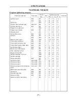
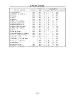
Part to be tightened
Part name
Thread
size
Q’ty
Tightening torque
Remarks
Nm
m.kg
ft · lb
Coolant reservoir
Bolt
M6 2 7 0.7 5.1
Radiator bracket and frame
Bolt
M6 4 7 0.7 5.1
Fuel pump
Bolt
M6 2 7 0.7 5.1
Fuel tank
Bolt
M8 2 30 3.0 22
Muffler stay
Bolt
M6 2 11 1.1 8.0
Muffler and exhaust pipe
Bolt
M8 1 20 2.0 14
Muffler bracket and muffler
Bolt
M8 2 20 2.0 14
Muffler bracket and frame
Bolt
M8 2 20 2.0 14
Muffler damper and muffler
Bolt
M6 1 10 1.0 7.2
Muffler damper and frame
Bolt
M6 1 10 1.0 7.2
Exhaust pipe
Nut
M8
2 14 1.4 10
Air duct assembly 1
Bolt
M6 2 7 0.7 5.1
Air duct assembly 2 and left protector
Bolt
M6 1 7 0.7 5.1
Air duct assembly 2 and frame
Bolt
M6 1 7 0.7 5.1
Gear position switch
Bolt
M5 2 7 0.7 5.1
Thermo switch 1 (cylinder head)
—
1/8
1 8 0.8 5.8
Thermo switch 3 (radiator)
—
M18
1 28 2.8 20
Reverse switch
—
M10
1 20 2.0 14
Engine ground lead
Bolt
M6 1 10 1.0 7.2
Starter motor and engine
Bolt
M6 2 10 1.0 7.2
.
Summary of Contents for HS200UTV
Page 3: ......
Page 15: ......
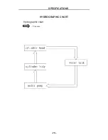
Page 94: ... 79 SPECIFICATIONS 79 HYDROGRAPHIC CHART Hydrographic chart Pressure ...
Page 95: ... 80 SPECIFICATIONS 80 LUBRICATION OIL WAY LUBRICATION OIL WAY Pressure splashing oil ...
Page 248: ... 233 CHASSIS 233 Fuel tank cap Remove the fuel tank cap by turning it counterclockwise ...
Page 263: ... 248 ...
Page 304: ... 289 ...
Page 305: ... 290 ...
Page 306: ... 291 ...
Page 307: ... 292 ...
Page 308: ... 293 ...
Page 309: ... 294 ...
Page 310: ... 295 ...
Page 311: ... 296 ...

