-24-
MN1-1014 Rev. 14
a
4-2. Attaching of the puncture adapter
Insert the puncture adapter, and turn the knob clockwise.
4-3.
Usage of the needle stopper and the depth gauge
Use of the needle stopper and the depth gauge can prevent the needle tip being inserted beyond the
pre-measured depth (target puncture region).
To use the needle stopper and the depth gauge, follow the procedure below.
(1) Display the puncture guide line on the monitor screen.
(2) Adjust the position and angle of the probe so that the target puncture region appears over the puncture
guide line on the display, and then freeze the image.
(3) Measure the distance "
a"
from the reference point of the puncture guide line on the monitor screen to the
target puncture region.
Use the puncture guide distance measurement function of the ultrasound diagnostic instrument.
Remarks:
For details on the method of measuring the distance using the displayed puncture guide line and calipers,
see the instruction manual of the ultrasound diagnostic instrument.
Reference point of the puncture
guide line.
Target puncture region
Image on the monitor screen
(1) The knob tip is passed through the needle guide hole.
Then attach the knob to the needle guide by turning the knob clockwise by six rotations or more.
(2) The puncture adapter boss and the knob tip is inserted in the probe hole.
Then attach the puncture adapter to the probe by turning the knob clockwise until stopping while pushing
the knob.
Puncture adapter boss
Probe hole
Knob tip
Needle guide hole
①
①
②
②
Summary of Contents for UST-9113P-3.5
Page 2: ...MN1 1014 Rev 14 ii ...
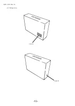
Page 16: ... 10 MN1 1014 Rev 14 2 Storage case Label A Label B ...
Page 18: ... 12 MN1 1014 Rev 14 ...
Page 24: ... 18 MN1 1014 Rev 14 ...
Page 46: ... 40 MN1 1014 Rev 14 ...
Page 48: ... 42 MN1 1014 Rev 14 ...
Page 52: ... 46 MN1 1014 Rev 14 ...
Page 54: ... 48 MN1 1014 Rev 14 ...

