background image

6

English

3. Moving the saw straight at a constant speed will

produce optimum cutting.

CAUTIONS

Before starting to saw, ensure that the saw
blade has reached full speed revolution.

Should the saw blade be stopped or made an
abnormal noise during operation, turn off the
switch immediately.

Always take care in preventing the power cord
from coming near the revolving saw blade.

MOUNTING AND DISMOUNTING THE SAW
BLADE

CAUTION

TO avoid serious accident, ensure the switch is in the
OFF position, and the power source is disconnected.

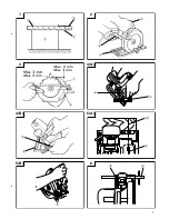
1. Dismounting the saw blade

(1) Set the cutting volume at maximum, and place the

Circular Saw as shown in 

Fig. 8

.

(2) Depress the lock lever, lock the spindle, and remove

the hexagonal-head bolt with the box wrench.

(3) While holding the safety cover lever to keep the

safety cover fully retracted into the saw cover,
remove the saw blade.

2. Mounting the Saw Blade:

(1) Thoroughly remove any sawdust which has

accumulated on the spindle, bolt and washers.

(2) As shown in 

Fig. 9

, the side of Washer (A) with

a projected center the same diameter as the inner
diameter of the saw blade and the concave side
of Washer (B) must be fitted to the saw blade sides.
*

Washer (A) is supplied for 2 types of saw blades
with the inner diameters of 16 mm and 30 mm.
(When buying the Circular Saw, one type of
washer (A) is spplied.)
In case the inner diameter of your saw blade
does not correspond to that of washer (A), please
contact the shop where you purchased the
Circular Saw.

(3) To assure proper rotation direction of the saw blade,

the arrow direction on the saw blade must coincide
with the arrow direction on the saw cover.

(4) Using the fingers, tighten the hexagonal-head bolt

retaining the saw blade as much as possible. Then
depress the lock lever, lock the spindle, and
thoroughly tighten the bolt.

CAUTION

After having attached the saw blade, reconfirm that the
lock lever is firmly secured in the prescribed position.

MAINTENANCE AND INSPECTION

1. Inspecting the saw blade:

Since use of a dull saw blade will degrade efficiency
and cause possible motor malfunction, sharpen or
replace the saw blade as soon as abrasion is noted.

2. Inspecting the mounting screws:

Regularly inspect all mounting screws and ensure
that they are properly tightened. Should any of the
screws be loose, retighten them immediately. Failure
to do so could result in serious hazard.

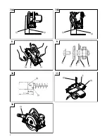
3. Inspecting the carbon brushes (Fig. 10)

The motor employs carbon brushes which are
consumable parts. Since an excessively worn carbon
brush can result in motor trouble, replace the carbon

brush with a new one having the same carbon
brush No. shown in the figure when it becomes
worn to or near the “wear limit”. In addition, always
keep carbon brushes clean and ensue that they
slide freely within the brush holders.

4. Replacing carbon brushes:

Disassemble the brush caps with a slotted-head
screwdriver. The carbon brushes can then be easily
removed.

5. Maintenance of the motor

The motor unit winding is the very “heart” of the
power tool.
Exercise due care to ensure the winding does not
become damaged and/or wet with oil or water.

6. Adjusting the base and saw blade to maintain

perpendicularity:

The angle between the base and the saw blade has
been adjusted to 90°, however should this
perpendicularity be lost for some reason, adjust in
the following manner:

(1) Turn the base face up (

Fig. 11

) and loosen the knob

and wing-bolt (

Fig. 4 (A)

Fig. 4 (B)

).

(2) Apply a square to the base and the saw blade and

turning the slotted set screw with a slotted-head
screwdriver, shift the position of the base to produce
the desired right angle.

NOTE

Due to HITACHI’s continuing program of research and
development, the specifications herein are subject to
change without prior notice.

IMPORTANT

Correct connection of the plug
The wires of the main lead are coloured in accordance
with the following code:

Blue:

– Neutral

Brown:

– Live

As the colours of the wires in the main lead of this tool
may not correspond with the coloured markings
identifying the terminals in your plug proceed as follows:
The wire coloured blue must be connected to the terminal
marked with the letter N or coloured black.
The wire coloured brown must be connected to the
terminal marked with the letter L or coloured red.
Neither core must be connected to the earth terminal.

NOTE

This requirement is provided according to BRITISH
STANDARD 2769: 1984.
Therefore, the letter code and colour code may not be
applicable to other markets except The United Kingdom.

Information concerning airborne noise and vibration

The measured values were determined according to
EN50144.

The typical A-weighted sound pressure level: 94 dB (A)
The typical A-weighted sound power level: 107 dB (A)

Wear ear protection.

The typical weighted root mean square acceleration value
does not exceed 2.5 m/s

2

.

Summary of Contents for FC 6SB

Page 1: ... Prima dell uso leggere attentamente e comprendere queste istruzioni Deze gebruiksaanwijzing s v p voor gebruik zorgvuldig doorlezen Leer cuidadosamente y comprender estas instrucciones antes del uso Handling instructions Bedienungsanleitung Mode d emploi Istruzioni per l uso Gebruiksaanwijzing Instrucciones de manejo CIRCULAR SAW KREISSÄGE SCIE CIRCULAIRE SEGA CIRCOLARE CIRKELZAAGMACHINE SIERRA C...

Page 2: ...1 3 4 B 2 4 A 5 B 1 1 2 4 3 8 7 2 9 5 A 6 0 4 A 9 B 6 2 2 6 5 ...

Page 3: ...2 7 A 8 10 12 7 B 9 11 C 0 0 F E 8 8 G 4 H I 43 6 mm 17 mm K J L 2 M N D ...

Page 4: ...á poussière 1 2 3 4 5 6 7 8 9 0 A B C D E F G H I J K L M N 1 2 3 4 5 6 7 8 9 0 A B C D E F G H I J K L M N 3 Italiano Nederlands Español Legno Zaaghout Madera útil Base Basisplaat Base Banco di lavoro Werkbank Banco de trabajo Lame della sega Zaagblad Cuchilla de sierra Mano Handgreep Mango Manopola Knop Perilla Coltello Splijtwig Cuchilla hendidora Bullone esagonale Zeskantige bout Perno de cabe...

Page 5: ... When not in use before servicing and when changing accessories such as blades bits and cutters 16 Remove adjusting keys and wrenches Form the habit of checking to see that keys and adjusting wrenches are removed from the tool before turning it on 17 Avoid unintentional starting Do not carry a plugged in tool with a finger on the switch Ensure switch is off when plugging in 18 Use outdoor extensio...

Page 6: ...g depth and then securely retighten the knob 2 Adjusting the riving knife Loosen the hexagonal head bolt used to clamp the riving knife adjust the riving knife to the position shown in Fig 3 and securely retighten the bolt 3 Adjusting the angle of inclination As shown in Fig 4 A Fig 4 B by loosening the knob on the incline gauge and the wing bolt on the base the saw blade may be inclined to a maxi...

Page 7: ...en them immediately Failure to do so could result in serious hazard 3 Inspecting the carbon brushes Fig 10 The motor employs carbon brushes which are consumable parts Since an excessively worn carbon brush can result in motor trouble replace the carbon brush with a new one having the same carbon brush No shown in the figure when it becomes worn to or near the wear limit In addition always keep car...

Page 8: ...s Gleichgewicht bewahren 14 Die Werkzeuge sollten sorgfältig behandelt werden Für einen einwandfreien und sicheren Betrieb sollten sie stets scharf sein und saubergehalten werden Die Anleitungen für schmierung und Austausch des Zuehörs unbedingt einhalten Die Kabel der Geräte regelmäßig überprüfen und bei Beschädigung durch eine autorisierte Kundendienststelle reparieren lassen Ebenfalls die Verlä...

Page 9: ...der Schnittiefe Mit der einen Hand den Stellknopf lösen und dabei wie in Abb 2 dargestellt mit der anderen Hand das Werkzeug am Handgriff halten Die Kerbentiefe kann durch Ausrichten der Auflage in die gewünschte Position eingestellt werden Die Schnittiefe auf diese Weise einstellen und anschließend den Stellknopf wieder festziehen 2 Einstellen des Spaltkeils Die Sechskantmutter mit der der Spaltk...

Page 10: ...ltende Sechskantkopfschraube von Hand so fest wie möglich anziehen Anschließend den Sicherungshebel herunterdrücken die Achse verriegeln und die Schraube fest anziehen VORSICHT Nach dem Anbringen des neuen Sägeblattes sich vergewissern daß der Sperrhebel in die vorgeschriebene Position gestellt ist WARTUNG UND INSPEKTION 1 Inspektion des Sägeblattes Da durch ein stumpfes Sägeblatt die Leistung abn...

Page 11: ...r régulièrement les rallonges et les remplacer si elles sont endommagées Veiller à ce que les poignées soient toujours sèches et propres sans huile ni graisse 15 Debrancher les outils lorsqu on ne les utilise pas avant toute opération d entretien et lors du changement d accessoire comme par exemple quand on change les lames les forets le fraises etc 16 Retirer les clés de réglage Prendre l habitud...

Page 12: ... éviter un possible accident s assurer toujours que la portion de bois restant après la coupe est bien ancrée ou maintenue en place REGLAGE AVANT LE TRAVAIL 1 Réglage de la profondeur de coupe Desserrer le bouton d une main tout en tenant la poignée de l autre comme illustré à la Fig 2 Il est possible d ajuster la profondeur de la fente en déplaçant la base sur la position souhaitée Régler de cett...

Page 13: ... boulon ATTENTION Lorsque la lame de la scie est montée vérifier que le levier de blocage est bien fixé dans la position indiquée ENTRETIEN ET CONTROLE 1 Contrôle de la lame Comme une lame émoussée diminue l efficacité et peut provoquer un mauvais fonctionnement aiguiser et remplacer la lame dès que des traces d abrasion sont visibles 2 Contrôle des vis de montage Vérifier régulièrement les vis de...

Page 14: ...a Tenerli sempre puliti ed affilati per un funzionamento migliore e più sicuro Seguire le istruzioni date per la lubrificazione e la sostituzione degli accessori Controllare periodicamente le condizioni del cavo della corrente Se dovesse essere rovinato farlo sostituire presso un Centro Assistenza Non usare cavi di prolungamento rovinati Mantenere le impugnature sempre pulite libere soprattutto da...

Page 15: ...no che resta dopo il taglio sia ben ancorata o tenuta in posizione REGOLAZIONI PRIMA DEL TAGLIO 1 Regolazione della profonditá di taglio Allentare la manopola con una mano tenendo l altra mano sull impugnatura come mostrato in Fig 2 La profondità della fessura può essere regolata spostando la base sulla posizione desiderata Regolare la profonditá di taglio quindi riserrare a fondo la manopola 2 Re...

Page 16: ... circolare Quindi premere la leva di bloccaggio bloccare l alberino e serrare saldamente il bullone ATTENZIONE Dopo aver attaccato la lama della sega controllare di nuovo che la leva di bloccaggio sia bloccata fermamente nella posizione prescritta MANUTENZIONE E CONTROLLI 1 Controllo della lama Poiché l uso di lame logose diminuisce l efficacia e causa eventuali disfunzioni del motore affilare o s...

Page 17: ...vrij om het gereedschap te bedienen 13 Buig u nooit te ver naar voren Kies een goede plaats en behoud altijd uw evenwicht 14 Behandel het gereedschap voorzichtig Zorg ervoor dat het gereedschap scherp en schoon is zodat een goed en veilig prestatievermogen wordt verkregen Volg de gebruiksaanwijzing voor het smeren en het verwisselen van toebehoren Inspecteer de snoeren regelmatig op beschadiging e...

Page 18: ...k werkelijk stabiel is Een onstabiele ondergrond is gevaarlijk LET OP Om eventuele ongelukken te vermijden moet men er steeds op letten dat het na eht zagen overgebleven gedeelte van het gezaagde hout goed vastligt of op de plaats gehouden wordt INSTELLEN VAN HET GEREEDSCHAP VOOR GEBRUIK 1 Instellen van de zaagdiepte Draai de knop met uw hand los en houd met de andere hand de handgreep vast zoals ...

Page 19: ...op gelet worden dat de schakelaar op UIT staat en de stekker uit het stopcontact is 1 Verwijderen van het zaagblad 1 Stel met de basisplaat de zaag in op zijn maximale zaagdiepte en houd de zaag zoals aangegeven in Afb 8 2 Druk de borghendel in vergrendel de as en draai de moer met de zeskantige kop los met de bijgeleverde moersleutel 3 De hendel van het beschermdeksel wordt vastgehouden zodat het...

Page 20: ...tricas a la lluvia No usar herramientas eléctricas en lugares moja dos o húmedos Mantener el área de trabajo bien iluminada No utilice herramientas eléctricas cuando exista el riesgo de incendios o de explosión 3 Protegerse contra descargas eléctricas Evitar el contacto del cuerpo con las superficies puestas a tierra p ej tubos radiadores hornos de microondas o refrigeradores 4 Mantener a los ni ñ...

Page 21: ...e indique lo contrario en este manual de instrucciones Procurar que los interruptores defectuosos los cambie un centro de reparaciones autorizado No usar las herramientas si sus interruptores no funcionasen apropiadamente 21 Advertencia La utilización de cualquier accesorio o aditivo no recomendado en este manual de instrucciones puede conducir al riesgo de lesiones 22 En caso de avería haga que s...

Page 22: ...justar la profundidad de corte y apretar firmemente la perilla 2 Ajustar la cuchilla partidora Soltar el perno de cabeza hexagonal para tensar la cuchilla partidora ajustar la cuchilla partidora a la posición como muestra en la Fig 3 y volver a apretar firmemente con el perno 3 Ajuste del ángulo de inclinación Como se muestra en la Fig 4 A y en la Fig 4 B aflojando la perilla del calibrador de inc...

Page 23: ...o se note el desgaste 2 Inspeccionar los tornillos de montaje Regularmente inspeccionar todos los tornillos de montaje y asegurarse de que estén apretados firmemente Si cualquier tornillo estuviera suelto volver a apretarlo inmediatamente El no hacer esto provocaría un riesgo serio 3 Inspección de escobillas de carbón Fig 10 El motor emplea carbones de contacto que son partes consumibles Como un c...

Page 24: ...23 Español The exploded assembly drawing should be used only for authorized service center ...

Page 25: ...g P 7 19 Bolt Washer M8 20 Riving Knife 21 Bolt W Flange M8 10 22 Diagonal Bolt M8 23 Seal Lock Flat Hd Screw M5 14 24 Knob 25 Machine Screw W Washers M4 10 26 Machine Screw W Washers M5 35 27 Tapping Screw W Flange D4 20 28 Name Plate 29 Housing Ass y 30 Switch 31 Noise Suppressor 32 Tube D 33 Brush Terminal 34 Stator Ass y 35 Fan Guide 36 Ball Bearing 608VVMC2EPS2L 37 Armature 38 Lock Lever 39 B...

Page 26: ...ca responsabilidad que este producto está de acuerdo con las normas o con los documentos de normalización EN50144 EN55014 y EN61000 3 según indican las Directrices del Consejo 73 23 CEE 89 336 CEE y 98 37 CE Esta declaración se aplica a los productos con marcas de la CE English EC DECLARATION OF CONFORMITY We declare under our sole responsibility that this product is in conformity with standards o...

Reviews: