5K250 (SATA) OEM Specification
Page 151 of 171
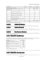
Command data structure: Data format of each command data structure is shown below.
Description
Bytes Offset
Device Control register
1
00h
Features register
1 01h
Sector count register
1
02h
LBA Low register
1
03h
LBA Mid register
1 04h
LBA High register
1
05h
Device register
1 06h
Command register
1
07h
Timestamp(milliseconds from Power On)
4
08h
12
Table 119 Command data structure
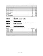
Error data structure: Data format of error data structure is shown below.
Description
Bytes Offset
Reserved
1 00h
Error register
1 01h
Sector count register
1
02h
LBA Low register
1
03h
LBA Mid register
1 04h
LBA High register
1
05h
Device register
1 06h
Status register
1 07h
Extended error data (vendor specific)
19
08h
State
1 1Bh
Life timestamp (hours)
2
1Ch
30
Table 120 Error data structure
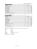
State field contains a value indicating the device state when command was issued to the device.
Value
State
x0h
Unknown
x1h
Sleep
x2h
Standby
x3h
Active/Idle
x4h
S.M.A.R.T. Off-line or Self-test
x5h-xAh
Reserved
xBh-xFh
Vendor specific
Note:
The value of x is vendor specific

