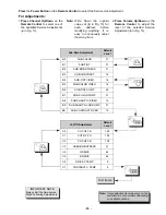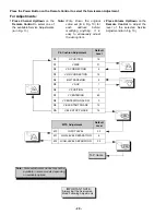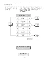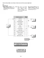
- 29 -
Color Temperature Adjustment
(B/W Tracking)
Serviceman DAC Adjust. (C0) (C1) (C2) (C4) (C5)
Minor Touch-Up Method
OBSERVE low and high brightness areas of a B/W
picture for proper tracking. Adjust only as required for
“good gray scale and warm highlights”.
1.
LOW LIGHT areas – In Serviceman Mode for
making electronic adjustments, select Cutoff (C0)
RED, (C1) GRN, (C2) BLU and adjust the picture
for gray.
2.
HIGH LIGHT areas – In Serviceman Mode for
making electronic adjustments, select Drive (C4)
GRN, (C5) BLU and adjust the picture for warm
whites.
Complete Adjustment
Preparation:
1.
Turn the Receiver “ON” and allow 10 minutes
warm up at high brightness.
2.
Apply a color bar signal with color “OFF”.
3.
Turn the SCREEN control (part of FBT T551) fully
counterclockwise.
Procedure:
Preset the following Serviceman DACs for best results:
• C0 . . . . . . . . . . . . . . 128
• C1 . . . . . . . . . . . . . 128
• C2 . . . . . . . . . . . . . . 128
• C4 . . . . . . . . . . . . . . 64
• C5 . . . . . . . . . . . . . . 64
1.
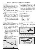
Connect the oscilloscope to C1-2 (CRT-Board).
2.
In Serviceman Mode for making electronic
adjustment, select the Sub-Bright DAC (B2).
3.
Press the LST-CH key on the remote.
4.
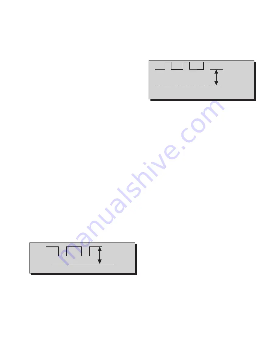
Observe the oscilloscope waveform at Horizontal
rate and adjust the Serviceman Mode Sub-Bright
DAC (B2) level until a scanning period of 2.5V
above DC ground is measured, as indicated in
Fig. 21.
5.
Connect the scope to RED Cathode (KR) on the
CRT-Board.
6.
In the Serviceman Mode for making electronic
adjustments, select the RED CUTOFF DAC (C0).
7.
Press the LST-CH key on the remote.
8.
View scope trace at Horizontal rate and adjust the
Serviceman Mode DAC (C0) level until a scanning
period of 195V above DC ground is measured, as
indicated in Fig. 22.
9.
Connect the scope to the GRN Cathode (KG).
10. In Serviceman Mode for making electronic
adjustments, select the GRN CUTOFF DAC (C1).
11. Press the LST-CH key on the Remote
12. View the scope trace and adjust the Serviceman
Mode DAC (C1) for the scanning period to be 195V
above DC ground. (See Fig. 22)
13. Connect the scope to the BLU Cathode (KB).
14. In Serviceman Mode for making electronic
adjustments, select the BLU CUTOFF (C2).
15. Press the LST-CH key on the Remote.
16. View the scope trace and adjust the Serviceman
Mode DAC (C2) for the scanning period to be 195V
above DC ground. (See Fig. 22)
17. Turn the Screen Control (part of FBT) slowly
clockwise until a color horizontal line appears.
18. With the other two colors Serviceman Mode DAC
CUTOFF adjustments (C0) RED, (C2) BLU;
increase the colors to create a white horizontal line.
19. Confirm that a good gray scale is established by
viewing B/W color bar pattern.
20. In the Serviceman Mode for making electronic
adjustments select the DAC DRIVE adjustments
(C4) GRN, (C5) BLUE and adjust for warm white in
a white color bar pattern.
21. EXIT the Serviceman Mode.
22. Adjust the Picture Menu Video Adjustments
Brightness and Contrast from low scale to high
scale and check Black and White tracking.
23. If correction is needed: Re-Enter the Serviceman
Mode and perform the Minor Touch – Up Method.
24. Perform Sub-Brightness Adjustment procedure if
needed.
0V DC
Figure 21. TP35 Waveform
2.5V DC
Figure 22. Cathode Waveform, Adjustment
Waveform Detail
195V DC
0V DC
(Ground)
Summary of Contents for 27GX01B-501
Page 47: ... 47 NOTES ...

