background image

SPECIFICATIONS AND PARTS ARE SUBJECT TO CHANGE FOR IMPROVEMENT.


LCD Display

January  2006

   Digital Media Division

YK

No.024E

32LD380TA

SERVICE MANUAL

LOCATION OF CONTROL ---------------------------- 3
REMOTE CONTROL ----------------------------------- 4
GENERAL SPECIFICATIONS ----------------------- 5
DISASSEMBLY INSTRUCTIONS ----------------- 11
SERVICE MODE LIST ------------------------------- 13
WHEN REPLACING EEPROM -------------------- 13
ELECTRICAL ADJUSTMENTS -------------------- 14

BLOCK DIAGRAM ------------------------------------ 17
PRINTED CIRCUIT BOARDS ---------------------- 23
INTERCONNECTION DIAGRAM ----------------- 29
MECHANICAL EXPLODED VIEW ---------------- 30

MECHANICAL REPLACEMENT PARTS LIST

 ------- 33

ELECTRICAL REPLACEMENT PARTS LIST

 -------- 35

Contents 

Be sure to read this manual before servicing. To ensure safety from 

fi

 re, electric shock, injury, harmful 

radiation and materials, various measures are provided in this Plasma Monitor.
Be sure to read cautionary items described in the manual before servicing.
These servicing instructions are for use by quali

fi

 ed service personnel only. To reduce the risk of electric 

shock, do not perform any servicing other than that described in the operating instructions unless you 
are quali

fi

 ed to do so.

Caution


1. Since the Panel Module and the front Filter are made of glass, handling the broken Module and Filter 

carefully and with caution in order not to receive injury.

2. Replacement work should be started after the Panel Module and the AC/DC Power supply have 

become suf

fi

 ciently cool.

3. Special care should be taken when working near the display area in order not to damage its surface.
4. The Panel Module should not be touched with bare hands in order to protect its surface from 

blemishes and damage.

5. It is recommended that you use clean soft gloves during the replacement work in order to protect not 

only the display area of the Panel Module but also yourself.

Service Warning


The LCD panel made from AUO is used for this product.

Summary of Contents for 32LD380TA

Page 1: ...vicing instructions are for use by qualified service personnel only To reduce the risk of electric shock do not perform any servicing other than that described in the operating instructions unless you are qualified to do so Caution 1 Since the Panel Module and the front Filter are made of glass handling the broken Module and Filter carefully and with caution in order not to receive injury 2 Replac...

Page 2: ...r take damage by electric shock if you touch to live part Use recommended components Please use to same characteristic com ponent which is same as previous for your safety and keep reliability espe cially marked by in parts list and cir cuit diagram It is reason of electric shock or fire if you use non recommended compo nent Should be kept same style of wiring or component Monitor uses tubes or ta...

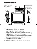
Page 3: ...n S video connector use an S video cable instead of a standard yellow video cable You still must connect the standard red and white audio cables for full system connection but do not connect a standard yellow video cable at the same time or the picture performance will be unacceptable 8 Main Power Switch To turn the unit on or off completely 9 Loudspeakers 10 Remote sensor 11 STANDBY ON mode indic...

Page 4: ...selection Call Menu Select TV channel or Teletext page step by step In Menu Setting In Standby Turning on the unit Volume In Menu Setting Memorize Select input source Two Channel Sound AUDIO 1 2 selector Teletext page 100 Teletext ON Mix OFF Reset Sound Picture Teletext enlargement Program position skipping Answer a Quiz Teletext Timer display Hold the text page Fastext TOPtext buttons Select pict...

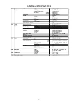
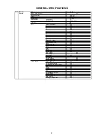
Page 5: ... 38 9 38 9 38 9MHz Sound FS 33 4 32 9 32 4 34 4MHz FP FS 5 5 6 0 6 5 4 5MHz Auto Tuning Method ALL Band Not C C I R CH Plan Preset CH 110 Stereo Dual TV Sound NICAM A2 Dual Tuner Sound Muting Yes G 3 Power Power Source AC 100 240V AC 50 60Hz DC Power Consumption at AC 150 W at AC 100 240 V 50 60 Hz at DC Stand by at AC 1 W at AC 100 240 V 50 60 Hz Per Year kWh Year Energy Star Yes Protector Power ...

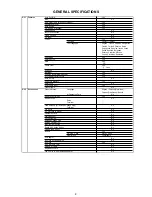
Page 6: ...light Yes Text Language Yes Language Yes Position Vertical Position Yes Auto 4 3 Default No AV2 Output No AV2 Input No Color System AV Color Yes Inversion No Screen Wipe Full White No Screen Saver No Static Image No Option Yes On Timer Yes Off Timer Yes Panel Lock Yes Menu PC Yes Picture Yes Brightness Yes Contrast Yes HOR Position Yes VER Position Yes Clock Phase Yes Horizontal Clock Yes AUTO ADJ...

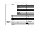
Page 7: ...mplitude Green Yes Amplitude Blue Yes Backlight Yes Nicam ST Yes Tone 1 2 Yes Pin Code No Freeze No CH AV PC Yes Hotel Lock No Wide Mode Yes Sleep Timer Yes Sound Mute Yes Input Select Yes NOT AVAILABLE Yes G 8 OSD Language English Chinese Simplified Chinese Traditional Russia G 9 Clock and Sleep Timer Max Time 120 Min Timer Step 10 Min On Off Timer Program On Timer Off Timer 1 Program Wake Up Tim...

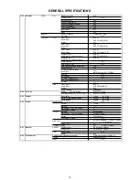
Page 8: ...Yes 7 Yes 8 Yes 9 Yes 0 Yes Volume Up Right Yes Volume Down Left Yes Sleep Yes Recall CH Call Yes Menu Yes Enter Yes Mute Yes Picture Size Yes Fine Tuning No Fine Tuning No Input Select Yes Multi Picture No Picture Position No Picture Main Sub No T TEXT Keys TEXT MIX TV Yes CH Up Page Up Up Yes CH Down Page Down Down Yes Red Yes Green Yes Yellow Yes Blue Yes F T B Expand Normal Yes Reveal Skip Yes...

Page 9: ...able Sound Yes PFC Power Factor circuit Yes Auto Set Up No Power On Memory Yes Hotel Lock No PC Monitor Input Yes Freeze frame No G 12 Accessories Owner s Manual Language English Chinese Simplified Chinese Traditional Russia w Guarantee Card No Remote Control Unit Yes Rod Antenna No Poles Terminal Loop Antenna W Antenna Change Plug No Terminal U V Mixer No DC Car Cord Center No Guarantee Card No W...

Page 10: ...Diversity No Ext Speaker No DC Jack 12V Center No VHF UHF Antenna Input DIN Type AC Inlet Yes Side Video Input 3 RCA x 1 Audio Input RCA x2 L MONO R S Input Yes Other Terminal Headphone G 14 Set Size Approx W x D x H mm 822 x 332 5 x 604 w o Stand Handle Approx W x D x H mm 822 x 115 x 556 5 G 15 Weight Net Approx 19 0kg 41 9 lbs Net w o Stand Handle Approx 16 5kg 36 4 lbs Gross Approx 23 0kg 50 7...

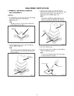
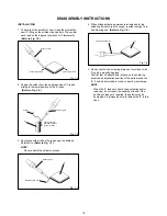
Page 11: ...e IC leads using a blower type IC desoldering machine Refer to Fig 1 2 2 Fig 1 2 NOTE Do not rotate or move the IC back and forth until IC can move back and forth easily after desoldering the leads completely When IC starts moving back and forth easily after desoldering completely pickup the corner of the IC using tweezers and remove the IC by moving with the IC desoldering machine Refer to Fig 1 ...

Page 12: ...Thin tip Soldering Iron NOTE When the IC leads are bent during soldering and or repairing do not repair the bending of leads If the bending of leads are repaired the pattern may be damaged So always be sure to replace the IC in this case Finally confirm the soldering status on four sides of the IC using a magnifying glass Confirm that no abnormality is found on the soldering position and installat...

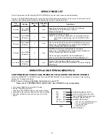
Page 13: ...justment MENU on the screen Refer to the ELECTRICAL ADJUSTMENT On Screen Display Adjustment Check of the SUM DATA and MICON VERSION on the screen Refer to the CONFIRMATION OF CHECK SUM POWER ON TOTAL HOURS AND MICON VERSION VOL DOWN Minimum 2 sec TV mode 2 1 2 3 4 FIG 1 Initialsetting data check sum POWER ON total hours 16 x 16 x 16 x thousands digit value 16 x 16 x hundreds digit value 16 x tens ...

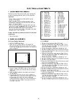
Page 14: ...remote control to select CONTRAST CENTER Check if the step No CONTRAST CENTER is 147 Receive a broadcast and check if the picture is normal Press the INPUT SELECT button on the remote control to set to the AV mode Activate the adjustment mode display of Fig 1 1 and press the channel button 35 on the remote control to select CONTRAST CENTER Check if the step No CONTRAST CENTER is 147 Receive a broa...

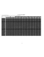
Page 15: ...128 128 128 128 17 G DRIVE W 128 128 128 128 128 128 128 128 128 128 128 128 128 128 128 128 128 128 128 128 128 128 18 G CUT OFF W 128 128 128 128 128 128 128 128 128 128 128 128 128 128 128 128 128 128 128 128 128 128 19 B DRIVE W 118 118 118 118 118 118 118 118 118 118 118 118 118 118 118 118 118 118 118 118 118 118 20 B CUT OFF W 128 128 128 128 128 128 128 128 128 128 128 128 128 128 128 128 ...

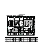
Page 16: ...4202 CD3807 CD3601 CD2201 CD4203 CORD CONNECTOR CU255502 CORD CONNECTOR CU2B1501 CORD JUMPER 2H0U0803 CORD JUMPER 2H0U0802 CORD CONNECTOR CU1K6001 CORD CONNECTOR CU235501 06CU255502 06CU2B1501 122H0U0802 122H0T0801 06CU1K6001 06CU235501 Item REF NO DESCRIPTION PART NO HITACHI PART NO 15 16 CD518 CD519 CORD CONNECTOR CU1B2002 CORD CONNECTOR CU252001 06CU1B2002 06CU252001 Item Board PART NO HITACHI ...

Page 17: ...TX OUT0 3 TXCLKOUT TXCLKOUT LCD PANEL V2301 T315XW01_V5 2 P CON 1 8V REG IC3202 BA00BC0WFP 6 1 4 P CON 3 8V P CON 3 3V P CON 1 8V SCALER_H 2 RED J4209 2 WHITE J4208 2 YELLOW J4207 SIDE_V_IN HP_OUT_R HEADPHONE JACK J4200 3 2 HP_OUT_L SYNC_SEPA Q8101 Q8102 Q8103 AV SWITCH 2 TUNER 21PIN STEREO SOUND AMP SW IC8103 MM1501XNRE SIDE_A_IN_R SIDE_A_IN_L S_VIDEO JACK J4206 3 2 SIDE_Y_IN SIDE_C_IN PSU_5VD PD...

Page 18: ...CART1_G_IN LEVEL SHIFT Q4208 Q4210 LEVEL SHIFT HP_OUT_R HP_OUT_L SCALER LVDS MICON ADC JACK SIDE JACK AV SWITCH 1 REGULATOR 17 13 15 V3 R V2 C V3 L 11 V2 Y SIDE_Y_IN SIDE_C_IN SIDE_A_IN_R SIDE_V_IN SIDE_A_IN_L DACA_L 25 DACA_R 24 AUDIO_OUT_JACK J4203 2 3 21 V4 R 19 V4 L 25 VDD2 VDD2 4 2 LINE IN L 18 19 HP OUT R HP OUT L 3 MUTE LINE IN R HEAD PHONE AMP IC IC300 NJM2151AV 3 6 5 8 16 11 9 14 1 HP_MUT...

Page 19: ...V or 24V 1 2 CP3801 5VSC 5VSC 5VSC 12VSC 12VSC 1 2 3 7 8 CP3803 9VSC 1 CP3802 ACD RLY ON 5CST_BY VS ON 5VD 1 2 3 5 6 CP3804 30V or 24V 3 3V CONTROL IC3801 AL1010 1 7 PSU_5VD VS_ON PDP_PLY POWER_FAIL P CON 12V AV SWITCH 2 TUNER 21PIN STEREO SOUND AMP CHOPPER Q3808 SCALER LVDS MICON ADC JACK SIDE JACK AV SWITCH 1 REGULATOR POWER ON H 7 POWER ON H STADBY_H 11 ST_BY_H 19 ...

Page 20: ... CP3601 6 D1 4 D1 12 10 CLK CLK 3 D2 1 D2 13 Pb 14 Y 7 8 12V DAC_A_L 1 5V 2 AUDIO L 16 Pr CD3601 3 10 12 DAC_A_R 4V AUDIO R 2 3 1 2 3 1 3 3VREG IC3601 KIA78D33F 2 3 1 3 3VREG IC3602 KIA78D33F BUFFER Q3603 6 7 5 8 SDA SCL WP VCC 3 2 4 1 BUFFER Q3604 SW Q3612 SW Q3613 Audio_In_L J3601 Audio_In_R J3602 4 3 1 2 L3601 ACM2012D L3603 ACM2012D L3602 ACM2012D L3604 ACM2012D 4 3 1 2 4 3 1 2 4 3 1 2 MICON2 ...

Page 21: ...5 SDATA SCLK LRCLK MCLK AOUT L VA AOUTR 3 8 7 6 EEP ROM IC IC3608 BR24L32F WE2 5 15 14 3 CSDA 2 CSCL BUFFER Q3605 4 SW IC3612 SN74AHC1G08DCKR 1 INTERFACE V_SYNC INTERFACE H_INT RXT_RST VDD5 CSDA BUFFER Q3606 CSCL 5 7 8 3 1 AUDIO_AMP IC3604 NJM4580M 18 MUTE_CTL MUTE SW Q3608 MUTE SW Q3610 MUTE SW Q3611 DAC_A_L DAC_A_R SDO SCK WS MCLK 12V X1 X2 2 1 4 6 4 GND A0 A1 A2 GND VCC WP SDA SCL 21 ...

Page 22: ...03 STR W6765 D S Vcc FB 24V INVERTER FEED BACK IC511 PS2561AL1 1 V W 3 2 4 1 REGULATOR IC501 KIA431A AT 2 3 1 SW Q512 P CON 12V 1 8 SW_CTL IC505 PQ1CX12H2ZPQ 3 2 1 4 9V_REGULATOR IC510 PQ090RDA1SZH 2 3 1 4 5V_REGULATOR IC509 PQ1CG3032FZH 2 3 1 4 5V_REGULATOR IC506 BA7810T V5 AT 5V LCD H P CON 5V FEED BACK IC512 PS2561AL1 1 V W 3 2 4 1 REGULATOR IC504 KIA431A AT 2 3 1 L511 PFC PRE REGULATOR IC501 E...

Page 23: ...303 CP301 CP4202 R4402 R4401 C 4 2 0 3 Q4229 Q4214 R4405 IC3804 C3823 D308 W910 W911 W912 W913 W914 C904_1 D4209 W922 W923 W924 R6507 R6501 CP4201 C307 C962 C963 R6004 R4222 R322 R323 Q300 Q302 R325 C906 C3805 C3825 C3826 C2202 W942 L3810 R6006 J4205 J4211 J4204 R4221 C919 R4236 R4235 R4226 R6015 R6011 J4202 J4203 J4210 C4273 D4205 L4218 L4219 L4214 L4212 C4409 C4411 R4295 C4413 L4216 L4217 L4213 ...

Page 24: ...915 C6507 R6010 R6009 R4409 R4410 C6002 R6018 R6017 R4201 W927 W930 R4413 R4414 R6003 R6002 R6001 R4415 W858 W884 R4237 Q4207 R4229 Q4209 C4219 Q4204 R4238 C4204 R4232 C4259_1 R4263 Q4201 Q4211 R4243 R4247 R4241 R4298 R4296 R4294 B4204 B4218 B4205 B4220 B4211 B4219 C4290 C4276 C4284 C4258 C4278 C4407 C4288 R4250 R4253 C4406 R4249 C4283 R4248 C4277 C4416_1 C4415_1 C4417_1 C4418_1 C4419_1 C4420_1 C4...

Page 25: ...W936 W937 C8170 C8118 W897 W914 C3204 R8149 R8150 C828 W905 W812 W811 W838 W881 W876 W839 W837 R4373 R4374 L4308 L4309 B8107 B8109 B8108 C2141 C4386 PRINTED CIRCUIT BOARDS SCALER TOP SIDE SCALER BOTTOM SIDE C822 C824 C823 C814 C837 C836 C838 C839 C841 C840 C812 C816 C826 C843 C842 C844 C818 C817 C845 C847 C846 C819 C820 C827 C2105 C2108 C2110 C2109 C2111 C2113 C2112 R2106 C2116 R2103 C2120 C2124 R...

Page 26: ...1 C583 C586 D545 D548 C578 L504 C600 IC504 R581 R629 W805 C595 C588 C589 L505 C582 D544 L503 C587 W804 IC511 R586 D549 D547 R609 C594 W014 D558 C592 D551 D557 R617 R607 W015 W021 W016 W022 W030 D550 D542 D543 D553 W018 W017 W008 W027 R589 CD517 CD518 CD519 CD520 CP502 D524 R546 R567 R641 W029 W813 C511 CP507 C593 W019 W814 W815 C503 R587 CP503 C525 C526 W037 D562 R647 R520 R535 W040 R663 C513 W025...

Page 27: ...4 R2201 R2202 R2203 R2206 R2204 R2205 IC501 R514 R511 C506 C505 R503 C502 C508 R504 C504 C512 C531 C535 R547 C539 R542 C533 C529 C538 R502 C597 R590 R602 R603 R598 C580 C579 C577 C599 C601 R628 R622 C604 R591 R604 R605 Q511 R595 R600 R594 C581 C584 Q515 R599 R615 R610 Q518 Q522 R626 Q521 R620 Q520 C602 C603 R601 R523 R527 Q504 C606 R645 R624 Q506 C590 C608 R655 Q505 B513 R659 R665 R666 R667 R510 R...

Page 28: ... C3668 C3671 R3659 R3662 R3664 C3676 C3674 C3663 C3664 B3609 R3657 C3667 C3672 R3661 R3663 C3675 R3660 C3673 B3611 B3610 R3669 L3604 L3602 L3603 L3601 C3613 C3614 C3622 C3619 C3617 C3618 C3620 C3625 C3626 C3604 C3628 C3632 C3658 C3680 IC3608 W812 W813 CP3604 D3601 D3603 IC3607 R3636 W820 W818 IC3605 C3652 C3651 C3650 CP3601 HS3601 J3601 J3602 R3675 C3683 R3674 C3682 R3678 Q3603 Q3604 Q3605 Q3606 Q...

Page 29: ...DE_S_Y SIDE_S_L GND GND SIDE_A_IN_R SIDE_A_IN_L SIDE_V_IN SIDE_S_C SIDE_S_Y SIDE_S_L P CON 5V CP3807 GND GND P CON 3 8V P CON 3 8V AT3 3V P CON 5V P CON 9V AT 5V GND P CON12V RED R Y C FROM TO POWER MODULE NC NC UC_SDA UC_SCL EN TX RX VCC GND RED WHITE CEE087 PCBDS0 SCALER PCB NC NC NC HDMI_1 2 HDMI_1 2 NC NC NC NC HDMI TX HDMI RX HDMI TX HDMI RX NC D2 D0 CLK SDA GND POWER D2 S D2 D1 D1 S D1 D0 D0...

Page 30: ... 208 208 208 107 102F 208 208 102B 102J 102I 102I 102G 102D 102E 201 206 208 208 208 208 208 208 102C 102K 201 210 113 210 113 101C 201 101D 101D 101E 101E 101F 101F 101A 101 PCBDA0 REMOCON PCB ASS Y 201 123 101B 201 201 201 201 PCB320 POWER SW PCB ASS Y 201 30 ...

Page 31: ...27 103B 202 202 209 209 209 209 103 103A 202 202 202 206 129 206 127 PCBF10 REGULATOR PCB ASS Y 203 203 206 206 206 206 PCBDJ0 HD MI PCB ASS Y 104 105 206 128 206 206 206 128 119 206 205 202 202 117 206 206 PCBD90 SIDE JACK PCB ASS Y 201 201 206 112 114 128 206 202 PCB270 OPERATION PCB ASS Y 206 206 204 204 204 204 204 204 203 PCB240 POWER PCB ASS Y 203 203 203 203 204 209 209 122 206 128 PCBD20 A...

Page 32: ...MECHANICAL EXPLODED VIEW PACKING DIAGRAM 143 140 134 144 138 136 135 141 142 133 136 139 137 137 BT001 002 CD3810 TM101 32 ...

Page 33: ...202 SCREW WASHER A M4 8 CH 3 s t r a p s t n e m e g n a r r a s u o n o r h c n y S 1 0 2 7 0 S T 1 2 1 5 1 0 2 0 2 0 2 S T 5 6 N O I H S U C 6 2 1 s t r a p s t n e m e g n a r r a s u o n o r h c n y S 1 1 2 7 0 S T 5 E R I W R E D L O H 7 2 1 s t r a p s t n e m e g n a r r a s u o n o r h c n y S 1 3 0 7 0 S T 1 O C L U P I L C D R O C 9 2 1 s t r a p s t n e m e g n a r r a s u o n o r h c n...

Page 34: ... 0 S T 1 2 K C A J E T A L P 0 2 1 1 9 2 7 0 S T 1 R E W O P N O T T U B 3 2 1 1 1 9 6 0 S T 1 1 P I L C G N I R I W 8 2 1 1 3 0 7 0 S T 1 O C L U P I L C D R O C 9 2 1 SMALL PART 201 SCREW TAP TITE P BRAZIER 3 10 CH 14 TS07062 202 SCREW WASHER A M4 8 CH 10 TS06923 203 SCREW TAP TITE B WH7 3 10 CH 12 TS07301 204 SCREW TAP TITE B WH8 3 10 CH 7 TS07302 5 6 0 7 0 S T 1 8 3 M N A P W E R C S 5 0 2 206...

Page 35: ...CTOR CU2E6601 1 TE03706 CD2201 CORD CONNECTOR CU235501 1 TE03707 CD3804 CORD CONNECTOR CU174001 1 TE03708 CD3806 CORD CONNECTOR CU145003 1 TE03831 CD3807 CORD CONNECTOR CU2B1501 1 TE03832 CD3810 CORD AC P320 0275 1 1 TE03402 CD4201 CORD CONNECTOR CU287001 1 TE03833 CD4202 CORD CONNECTOR CU255502 1 TE03834 CD4203 CORD JUMPER 2H0T0801 1 TE03416 CORD JUMPER 2H0T0802 1 TE03411 CD4204 CORD JUMPER 2H0U0...

Page 36: ...YK No 024E Printed in Japan JE VG06371 32LD380TA Digital Media Division ...

Reviews: