1
8
32PD5000/42PD5000 (PW1)
15
32PD5000/42PD5000 (PW1)
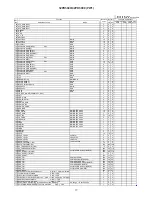
: should be adjusted
: should be followed previous data
Function
Maximum
Adjustment Items
Mode
Value
32" 42"
VIDEO
PWB
TUNER
PWB
PDP
Panel
178 Free
179 Free
180 Terminal Mode Function available
0:Not Available, 1:Available RS232C
1
0
0
181 Free
182 AGC_LEVEL
AGCL
ALL Mode
3
0
0
183 TEXT H sync delay
-
127
0
0
184 TEXT V sync delay
-
127
50 50
185 TEXT_H_POSITION
-
254
42 42
186 TEXT_V_POSITION
-
254
38 38
187 Lower Limits value for Sync Detect of 2ms interval
For AFC at TV mode
254
25 25
188 Upper Limits Value for Sync Detect of 2ms interval
For AFC at TV mode
254
40 40
189 Lower Limits value for Sync Detect of 2ms interval
For Free Running at TV mode
254
30 30
190 Upper Limits Value for Sync Detect of 2ms interval
For Free Running at TV mode
254
45 45
191 Lower Limits value for Sync Detect of 2ms interval
For AUTO OFF at TV mode
254
25 25
192 Upper Limits Value for Sync Detect of 2ms interval
For AUTO OFF at TV mode
254
35 35
193 Lower Limits value for Sync Detect of 2ms interval
For Free Running at AV mode
254
30 30
194 Upper Limits Value for Sync Detect of 2ms interval
For Free Running at AV mode
254
45 45
195 Counting time for discrimination of fV (TB1274)
-
31
2
2
196 Free
1
0
0
197 Counting time for discrimination of Sync. (M30625/TA1370)
-
31
2
2
198 Input Source of fV/fH judgment (0:M30625,1:TA1370)
Component Mode
1
0
0
199 Counting time for discrimination of fV (M30625/TA1370)
-
31
2
2
200 Y_DL (6.5MHz PAL/NTSC4.43)
Main
10
7
7
201 Y_DL (6.5MHz SECAM)
Main
10
10 10
202 Y_DL (6.5MHz PAL/NTSC4.43)
Sub
10
4
4
203 Y_DL (6.5MHz SECAM)
Sub
10
10 10
204 PDP-BLK ON/OFF
1:ON, 0:OFF
1
0
0
205 Counting time for discrimination of fH (M30625/TA1370)
-
31
2
2
206 Sharpness f0(L)
Sub
3
2
2
207 NJW1320_OUT1_GAIN
VIDEO PWB
1
0
0
208 NJW1320_OUT2_GAIN
VIDEO PWB
1
0
0
209 Sharpness f0(L')
Sub
3
2
2
210 AFC_GAIN (Except AV00 mode)
Except AV00 mode
3
0
0
211 Timer Correction (for error of ceramic-filter osc.freq.)
62
34 34
212 Brightness Center (CM)
NT2/NT3/HD2/HD3/PAL2/PAL3/HD9/HD10/NT4/PAL4
254
128 128
213 Brightness Center (CM)
HD1/HD4/HD5/HD6/HD7/HD8
254
124 124
214 Brightness Center (CM)
MULTI PICTURE/NT1/PAL1
254
128 128
215 Free
216 Contrast Center (CM)
TV/VIDEO(AV1/AV4 mode)
254
137 137
217 Free
218 Color Center (CM)
NT1/NT2/NT4/HD3/HD4/HD6/PAL4
127
80 80
219 Color Center (CM)
PAL1/PAL2/HD8/HD9
127
80 80
220 Color Center (CM)
NT3/HD1/HD2/HD5/PAL3/HD7/HD10
127
80 80
221 Tint Center (CM)
PAL1
254
118 118
222 Tint Center (CM)
NT1/NT2/NT4/HD3/HD4/HD6
254
120 120
223 Tint Center (CM)
PAL2/HD8/HD10/PAL4
254
115 115
224 Tint Center (CM)
NT3/HD1/HD2/HD5/PAL3/HD7/HD9
254
124 124
225 Center of Sharpness (HV Enhancer Gain for Y)
For Europe
TV
31
19 19
226 Center of Sharpness (HV Enhancer Gain for Y)
For Europe
VIDEO
31
18 18
227 Center of Sharpness (HV Enhancer Gain for Y)
For Europe
HD5/HD6
31
11 11
228 Center of Sharpness (HV Enhancer Gain for Y)
For Europe
HD1/HD4/HD7/HD8
31
7
7
229 Center of Sharpness (HV Enhancer Gain for Y)
For Europe
HD2/HD3/HD9/HD10
31
15 15
230 Center of Sharpness (HV Enhancer Gain for Y)
For Europe
NT2/NT3/PAL2/PAL3/NT4/PAL4
31
15 15
231 Center of Sharpness (HV Enhancer Gain for Y)
For Europe
TEXT(2 picture)
31
7
7
232 Maximum Value of Contrast at REAL/NORMAL mode
254
188 188
233 Offset Value of Contrast data at SPLIT mode
120
90 90
234 Offset value of gain for Black Stretch function
except OFF/LOW/HIGH
63
33 33
235 Demonstration [White]
0-3:None 4:0 5:+10W 6:+20W 7:+30W Mode(common)
7
5
5
236 Demonstration
0:Normal 1:Peak
Mode
1
1
-
237 Demonstration [Middle]
0:+0W 1:+10W 2:+20W 3:+30W
Mode(common)
3
3
3
238 Demonstration
0:Normal 1:Peak
Mode
1
-
0
239 Horizontal Enhance
TEXT
3
3
3
240 YNR Input Level at Low level
for DVI-STV Mode
1080i-60/1080i-50/720p-60
7
2
2
241 YNR Input Level at Low level
for DVI-STV Mode
480i/480p/576i/576p/VGA
7
2
2
242 CNR Input Level at Low level
for DVI-STV Mode
1080i-60/1080i-50/720p-60
7
2
2
243 CNR Input Level at Low level
for DVI-STV Mode
480i/480p/576i/576p/VGA
7
2
2
244 Vertical Enhance
TEXT
3
3
3
245 Demonstration Mode
0:off 1:on
1
0
0
246 Free
247 Free
248 HV Enhancer Gain for C
TEXT
31
0
0
249 YNR(NR) Input Level
RF Mode
7
1
1
250 YNR Input Level at Low level
for AV1-4 Mode
VIDEO
7
3
3
251 YNR Input Level at Low level
for AV1-4 Mode
NT2/NT3/PAL2/PAL3/NT4/PAL4
7
3
3
252 YNR Input Level at Low level
for AV1-4 Mode
HD1/HD4/HD5/HD6/HD7/HD8
7
3
3
253 YNR Input Level at Low level
for AV1-4 Mode
HD2/HD3/HD9/HD10
7
3
3
254 CNR Input Level at Low level
for AV1-4 Mode
VIDEO
7
3
3
255 CNR Input Level at Low level
for AV1-4 Mode
NT2/NT3/PAL2/PAL3/NT4/PAL4
7
3
3
256 CNR Input Level at Low level
for AV1-4 Mode
HD1/HD4/HD5/HD6/HD7/HD8
7
3
3
257 CNR Input Level at Low level
for AV1-4 Mode
HD2/HD3/HD9/HD10
7
3
3
258 Heat APC function available
0:NO, 1: YES
1
1
1
259 Gamma SW (0:1.0 1:2.2 2:2.8)
TV/VIDEO
2
1
1
260 Gamma SW (0:1.0 1:2.2 2:2.8)
DVI-PC/DVI-STB/DSUB-RGB
2
1
1
261 Select for APC function
1
0
0
262 "CCFMD" function
TV/VIDEO
1
0
0
263 "CCFMD" function
DVI-PC/DVI-STB/DSUB-RGB
1
0
0
264 NTSC/EBU(CCFORM)
NT1/NT2/HD3/HD4/HD6/HD8/HD10/PAL1/PAL2
1
0
0
265 NTSC/EBU(CCFORM)
TV/VIDEO/NT3/PAL3/HD1/HD2/HD5/HD7/HD9/NT4/PAL4
1
0
0
266 NTSC/EBU(CCFORM)
DVI-PC/DVI-STB/DSUB-RGB
1
0
0
Default
Changed Component
ADJ.
No.
FORMATTER
PWB
For Asia
For Asia
For Asia
For Asia
Summary of Contents for 32PD5000
Page 26: ...26 55PMA550 55HDM71 PW1 00E ...
Page 31: ...31 55PMA550 55HDM71 PW1 00E ...
Page 49: ...32PD5000 42PD5000 49 ...
Page 50: ...37P D5 00 0 50 ...
Page 51: ...55PMA550 51 ...
Page 52: ...32PD5000 42PD5000 52 ...
Page 53: ...55PMA550 55HDM71 53 ...
Page 54: ...32PD5000 42PD5000 54 ...
Page 55: ...32PD5000 42PD5000 55 ...
Page 56: ...32PD5000 42PD5000 56 ...
Page 57: ...55PMA550 55HDM71 57 ...
Page 58: ...32PD5000 42PD5000 58 ...
Page 59: ...55PMA550 55HDM71 59 ...
Page 67: ...67 32PD5000 42PD5000 11 Block diagram ...
Page 68: ...68 55PMA550E Block diagram ...
Page 72: ...72 55PMA550 12 Connection diagram PW1 55V CONNECTION DIAGRAM ...
Page 77: ...77 32PD5000 42PD5000 42PD5000 ...
Page 79: ...79 55PMA550 Wiring diagram Wiring diagram 1 2 ...
Page 80: ...80 55PMA550 Wiring diagram 2 2 ...
Page 83: ...83 32PD5000 42PD5000 42PD5000 ...
Page 84: ...84 37PD5200 37PD5000 ...
Page 85: ...85 55PMA550 14 Disassembly diagram ...
Page 89: ...89 55PMA550 ...
Page 90: ......
Page 91: ...THE UPDATED PARTS LIST FOR THIS MODEL IS AVAILABLE ON ESTA ...
Page 92: ...HITACHI SM005 Power Supply Block Diagram 92 ...
Page 93: ...HITACHI SM005 Panel Connectors 93 ...
Page 94: ...HITACHI SM005 Power Supply Circuit Board ...
Page 95: ...HITACHI SM005 Power Supply Circuit 1 of 5 ...
Page 96: ...HITACHI SM005 Power Supply Circuit 2 of 5 ...
Page 97: ...HITACHI SM005 Power Supply Circuit 3 of 5 ...
Page 98: ...HITACHI SM005 Power Supply Circuit 4 of 5 ...


