4
37PD5
2
00 (EU) (PW1)
PRECAUTIONS
● How to clean the plasma screen panel of the monitor
Before cleaning the monitor, turn off the monitor and disconnect the power plug from the power outlet.
To prevent scratching or damaging the plasma screen face, do not knock or rub the surface with sharp or hard
objects. Clean the screen with a soft cloth moistened with warm water and dry with a soft cloth. If it is not
enough, then use a cloth with mild detergent. Do not use harsh or abrasive cleaners.
● How to clean the cabinet of the monitor
Use a soft cloth to clean the cabinet and control panel of the monitor. When excessively soiled dilute a neutral
detergent in water, wet and wring out the soft cloth and afterward wipe with a dry soft cloth.
Never use acid/alkaline detergent, alcoholic detergent, abrasive cleaner, powder soap, OA cleaner, car wax,
glass cleaner, etc. especially because they would cause discoloration, scratches or cracks.
1. Features
PW1 chassis
This chassis basically constitutes just a MONITOR to use with AVC (Audio Visual Control center). But it can con-
stitute AV MONITOR when applied the VIDEO board, and also a TV when applied the VIDEO board and the
TUNER board.
[Common Features]
● Large-screen, high-definition plasma display panel
The 37-inch color plasma display panel, with a resolution of 1024 (H) x 1024(V) pixels, creates a high-definition, large-
screen (aspect ratio : 16:9) and low-profile flat display. Free from electromagnetic interferences from geomagnetic
sources and ambient power lines, the panel produces high-quality display images free from color misconvergence
and display distortion.
● High Performance Digital Processor
A wide range of personal computer signals can be handled, from 640 x 400, 640 x 480 VGA to 1600 x 1200 UXGA.
(RGB analog input)
● Easy-to-use remote control and on screen display system
The remote control included eases the work of setting display controls. Further, the on-screen display system,
displays the status of signal reception and display control settings in an easy-to-view fashion.
● Power saving system
The International ENERGY STAR power saver feature saves power consumption automatically when input sig-
nals are not available.
When connected to a VESA DPMS-compliant PC, the monitor cuts its power consumption while it is idle.
● TruBass
TruBass, SRS and ( ) symbol are trademarks of SRS Labs,Inc.
TruBass technology is incorporated under license from SRS Labs, Inc.
[AVC MONITOR model] 37PD5000
●
DVI-D terminal and 8pin-DIN terminal for AVC input
(Other terminals, buttons and remote control for use are all with the AVC unit.)
[TV model] 37PD5
2
00
●
One mini D-sub terminal and one DVI-D terminal for RGB input.
The D-sub terminal can also receive the RGB-component by On-Screen Display control.
●
One composite/S.video input terminal and two component video input terminals added with VIDEO board.
One component input is possible to switch to RGB signal input from the Menu screen.
●
One SCART terminal for the signal of the European standard added with VIDEO board.
It operates as composite/S.video input and RGB input terminal, or composite video output terminal.
●
One composite video output terminal as a monitoring output added with VIDEO board.
●
Tuner and TELETEXT receiver added with TUNER board.
●
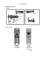
High performance type of the remote control
Summary of Contents for 32PD5000
Page 26: ...26 55PMA550 55HDM71 PW1 00E ...
Page 31: ...31 55PMA550 55HDM71 PW1 00E ...
Page 49: ...32PD5000 42PD5000 49 ...
Page 50: ...37P D5 00 0 50 ...
Page 51: ...55PMA550 51 ...
Page 52: ...32PD5000 42PD5000 52 ...
Page 53: ...55PMA550 55HDM71 53 ...
Page 54: ...32PD5000 42PD5000 54 ...
Page 55: ...32PD5000 42PD5000 55 ...
Page 56: ...32PD5000 42PD5000 56 ...
Page 57: ...55PMA550 55HDM71 57 ...
Page 58: ...32PD5000 42PD5000 58 ...
Page 59: ...55PMA550 55HDM71 59 ...
Page 67: ...67 32PD5000 42PD5000 11 Block diagram ...
Page 68: ...68 55PMA550E Block diagram ...
Page 72: ...72 55PMA550 12 Connection diagram PW1 55V CONNECTION DIAGRAM ...
Page 77: ...77 32PD5000 42PD5000 42PD5000 ...
Page 79: ...79 55PMA550 Wiring diagram Wiring diagram 1 2 ...
Page 80: ...80 55PMA550 Wiring diagram 2 2 ...
Page 83: ...83 32PD5000 42PD5000 42PD5000 ...
Page 84: ...84 37PD5200 37PD5000 ...
Page 85: ...85 55PMA550 14 Disassembly diagram ...
Page 89: ...89 55PMA550 ...
Page 90: ......
Page 91: ...THE UPDATED PARTS LIST FOR THIS MODEL IS AVAILABLE ON ESTA ...
Page 92: ...HITACHI SM005 Power Supply Block Diagram 92 ...
Page 93: ...HITACHI SM005 Panel Connectors 93 ...
Page 94: ...HITACHI SM005 Power Supply Circuit Board ...
Page 95: ...HITACHI SM005 Power Supply Circuit 1 of 5 ...
Page 96: ...HITACHI SM005 Power Supply Circuit 2 of 5 ...
Page 97: ...HITACHI SM005 Power Supply Circuit 3 of 5 ...
Page 98: ...HITACHI SM005 Power Supply Circuit 4 of 5 ...

