background image

Summary of Contents for 35UX85B/CZ68

Page 1: ...C rules TABLE OF CONTENTS SAFETY PRECAUTIONS 2 TROUBLESHOOTING FLOWCHARTS 25 PRODUCT SAFETY NOTICE 3 REPLACEMENT PARTS LIST 41 POWER SOURCE 3 WIRING DRAWING OF FINAL ASS Y 59 TECHNICAL SPECIFICATIONS 4 PRINTED WIRING BOARD FOIL PATTERN 60 TECHNICAL CAUTIONS 5 CIRCUIT SCHEMATIC DIAGRAM 62 ADJUSTMENT SPECIFICATIONS 6 SPECIFICATIONS AND PARTS ARE SUBJECTTO CHANGE FOR IMPROVEMENT SOLID STATE COLOR TEL...

Page 2: ...lation tester DCSOOV con nect one lead to the jumpered AC plug and touch the other lead to each exposed metal part antennas screwheads metal overlays control shafts etc particularly any exposed metal part having a return path to the chassis should have a minimum resistor reading of 0 24MQ and a maximum re sistor reading of 12MR Any resistance value below or above this range indicates an abnormalit...

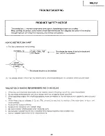
Page 3: ...ITACHI Service Manual may be obtained at a nominal charge from HITACHI SALES CORPORATION X Radiation TUBE The primary source of X Radiation in this receiver is the picture tube The tube utilized in this chassis is specially constructed to limit X Radiation emission For continued X Radiation protection the replacement tube must be the same type as the original HITACHI approved type When troubleshoo...

Page 4: ...dio Output Power Dimension Height in Width in Depth in Weight Ibs Circuit Board Assemblies Front 3 watts rms per channel 8 ohm impedance Max output 5 watts Rear 5 watts per channel 8 ohm impedance Max output 5 watts 35UX85B 29 132 35 24131zz 266 CPT P C B Signal P C B Signal Sub P C B Power Deflection P C B Power P C B DF P C B Deflection P C B Control A P C B Control B P C B Surround A P C B Surr...

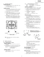
Page 5: ...V CZ68 fl KV M l mA 0 3v 1 3 KV Adjustment Preparation 4 Set AC input voltage to 120 3V Then connect the VR 1 OOK B and Rl 27K to R927 and ground side as below Note At that time the value of VR should be maximum Use the voltmeter of input impedance IOM ohm or more with indication to the 1st decimal place CPT Anode CPT High VoltageVoltmeter I DC Voltage Dwider 8 a A Digital Vollmeter c925 I R92 5 m...

Page 6: ... 4 4 Weak Electric Field Check 12 2 Power Supply and Main P W B 12 2 1 B Voltage Adjustment 12 2 2 Protection Circuit Operation Check 12 2 3 FBT Protection Circuit Operation Check 13 2 4 High Voltage Limiter Circuit 13 2 5 Side Pin Distortion Coarse Adjustment 13 2 6 H Size H Center Coarse Adjustment 14 2 7 Vertical Amplitude Coarse Adjustment 14 2 8 Discharge of 200V Line 14 II COMMON SERVICE ADJ...

Page 7: ...Equipment 19 3 1 Check in Combination with External Equipment 19 4 Polarity Check 20 Ill INITIAL SETTING FOR SHIPMENT 20 jlV ADJUSTMENT POINT LOCATIONS L 22 Refer to CHASSIS SERVICE MANUAL PA NO 0073 for additional technical information Note 1 MAIN CHASSIS ASSEMBLY ADJUSTMENT is done with precision equipment Readjustment is only recommended if the service technician replaced a defective component ...

Page 8: ...stment Preparation 1 Connect the jig shown below to the ANT A terminal 2 Turn on the sub picture Adjustment Procedure 1 Select main picture 2 Receive a standard carrier signal not offset with the channel UP DOWN or direct selection buttons Check that it is pulled into the standard tuning point 3 Receive an offset signal of 1 5MHz Check that it is pulled into the standard tuning point Perform the c...

Page 9: ... so that the VHF UHF CATV signal can be received Adjustment Procedure 1 Every time the POWER button is pressed the power should alternate between ON and OFF 1s3 3 2 CH UP DOWN Adjustment Procedure 1 Every time the CH UP A or CH DOWN v button is pressed the normal reception should be displayed for VHF UHF and CATV Check that the On Screen Display corresponding to the received contents can be displa...

Page 10: ...6 Check that clock indication is displayed using the RECALL button And the clock indication is going by 1 second per minute iig 1 3 4 Al mode operation check Adjustment Preparation 1 Receive the color bar signal 2 Select the VIDEO SETTINGS option using the b button 3 Select Advance settings option using the b button 4 Set the Ultra Al mode using the Av buttons Adjustment Procedure 1 Set the AI ON ...

Page 11: ...ck window appears and TEXT letters are displayed at the center of screen Repeat from 6 to 7 and check that TEXT letters are displayed Set the MODE to C C The black window should disappear Set the DISPLAY to OFF Check that the CAPTION letters disappear X Y 30mm ABCD _ L black window TEXT letter Remarks Receive signal having closed caption signal Reading error should not occur on any mode The conten...

Page 12: ...EZE key is pressed the sub picture alternates between moving picture and freezing picture 2 Turn to No Signal condition Adjustment Procedure I Check that phenomena such as oscjllation and abnormal beat etc do not occur on any channel Antenna Terminal board VHF UHF 75 ohm 300 ohm adaptor Moving picture Freezing picture Press PinP key to remove PinP from screen 1 3 6 5 PinP Freeze mode at PinP OFF A...

Page 13: ...s normally 2 4 High Voltage Limiter Circuit Operation Check Checking Preparation 1 Connect the assembly to a standard set 2 Connect a high voltage voltmeter between CPT anode terminal anode cap side and the ground 3 Set AC input voltage to 120f3V 4 Receive a circle pattern or color bar signal and set BRIGHTNESS and CONTRAST to maximum Adjust screen VR so that beam current is I O 1mA The voltage of...

Page 14: ...ss hatch signal vary R631 so that the top and bottom of the screen edge is 7 cross hatch away from the exact center of the cross hatch signal Adjustment position inner edge of the outer circle 2 8 Discharge of 200V Line Adjustment Preparation 1 After the adjustment of assembled P W B and after the checking of mounting the jig below is connected 2 Deflection P W B EY2 connector PY2 2oov 1 GND Adjus...

Page 15: ...a cross hatch 1 The TV set should face North or South 2 Receive circle pattern signal or cross hatch signal Cross hatch signal 20 vertical lines 14 horizontal lines Set CONTRAST control to maximum and BRIGHTNESS control to center Adjustment Procedure 1 Adjust V size VR R631 so that the outer circle pattern is like figure Note Perform this adjustment more than 5 minutes after applying the power ON ...

Page 16: ...low brightness white balance VRs except VR A and adjust so that red green and blue bright colored lines appear on the screen equally Return the switch S851 back to normal position Set CONTRAST and BRIGHTNESS controls to minimum and turn sub black level VR R325 to set at the position where the white raster is just slightly seen Set the white balance meter at the center of the screen Adjust CONTRAST...

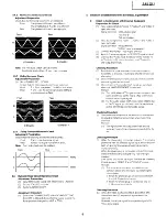
Page 17: ...lay and match the sub picture details with the main picture details by pressing FREEZE key of remote controller 3 Condition should be set as follows CONTRAST MAXIMUM OTHERS CENTER 1 4 White signal specification amplitude 1 OVpp Adjustment Procedure 1 2 3 4 Observe Q857 collector on the CPT P W B and turn the BLUE adjustment VR R5C7 and adjust so that the amplitude of the sub picture is the same as...

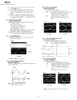
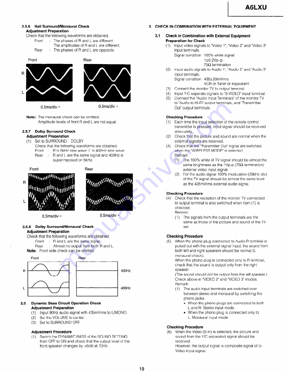
Page 18: ...urround Off Monaural Check Adjustment Preparation Check that the following waveform is obtained The amplitudes of 2 channels are equal Front Note Monaural check can be omitted REAR output is no signal 400Hz 400Hz 2 5 3 Matrix Surround Check Adjustment Preparation 1 Set to SURROUND MATRIX Check that the following waveforms are obtained Front Check that the phases of R and L are different and 400H z...

Page 19: ...arate signats to S VIDEO input terminal Connect the Audio Input Terminals of the monitor TV to Audio to Hi F output terminals and Transmitter Out output terminals Checking Procedure 1 Each time the input selection of the remote control transmitter is pressed input signal should be received alternately 2 Check that the picture and sound are normal when the external signals are received 3 Check that...

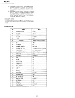
Page 20: ...d chassis earth III INITIAL SETTING 1 NO NAME SPEC 1 Reception Channel 03 CH 2 ANTENNA ANT A 3 INPUT TV 4 VOLUME 20 STEP 5 P IN P OFF I 6 P in P POSITION LOWER RIGHT P in P ON 7 cm OFF 8 Al R CABLE AIR 9 CHANNEL MEMORY 02 l 3 CH 10 CHANNEL CAPTION No Reqistered for all Channels I If CHILD LOCK I OFF for all Channels I 12 VOLUME CORRECTION 13 CLOCK SET OFF for all Channels OFF I 14 CONTRAST MAXIMUM...

Page 21: ...A6LXU Ill INITIAL SETTING 21 ...

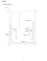
Page 22: ...AGLXU IV ADJUSTMENT POSITION LIST SIGNAL P W B 240 0 I 325 l I 325 SURROUND P W B 240 lul PI1 SUB SIGNAL P W B R5C7 B 0 R5C5 G 0 R5C3 R 0 2LINE COMB UNIT TERMINAL P W B P in P UNIT 0 I 0 22 ...

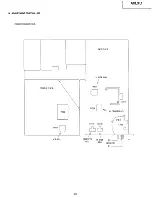
Page 23: ...IV ADJUSTMENT POSITION LIST POWER P W B DEF P W B POWER P W B IT902 I I R928 J BADJ DEF P W B V SIZE ADJ i R631 c I 0 Q711 R759 H CENTER ADJ R7HF R7H6 r 0 23 ...

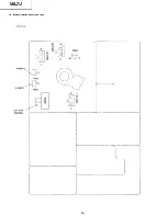
Page 24: ...IV ADJUSTMENT POSITION LIST P W 8 CPT R DRIVE I B DRIVE CUT OFF SWITCH R860 F R864 B 24 ...

Page 25: ...set and tester PRECAUTION ON MAKING MEASUREMENTS AND ON HANDLING 1 2 3 4 5 6 7 8 9 When any parts become abnormally hot or there is a smell of burning cut off the power immediately Do not make shorts between circuits or across terminals except for those specified When applying a signal for checking purposes make connection in the alternate current system for any not speci fied When measuring the v...

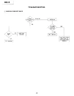
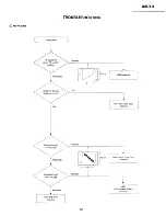
Page 26: ...AGLXU TROUBLESHOOTING POWER RELAY DOES NOTTURN ON About 15V R C Circuit NO YES I 26 ...

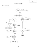
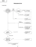
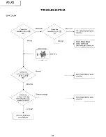
Page 27: ...A6LXU TROUBLESHOOTING NO RASTER AND SOUND About 320V at AC120V Open Normal DC 2V D991 El defective Short between C and E Normal v Normal iov 1901 1501 1001 defective ov 27 ...

Page 28: ...1501 F701 open n7n CDT lefective UILI rpl u waveform of 1501 No switching 0 7v High voltage protection circuit operating 1501 defective 1901 Q901 D901 T701 T702 DY C721 etc 9V Line defective C629 shorted 1401 defective 1902 defective Q72 l defective 28 ...

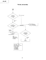
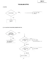
Page 29: ...TROUBLESHOOTING NO PICTURE Does On Screen No 1501 1001 1006 2024 defective Is waveform of Normal t c Abnormal Is waveform of Normal i Abnormal Front end IYOI defective 29 ...

Page 30: ...ning circuit defective No sync or distorted picture I I Front End 1501 and peripheral parts defective No raster or dark Front End IYOI QCOI Q5A3 Q5A4 Q5A5 Q5A6 and peripheral parts defective 1 CPT P W B CPT FBT 1 Lower than 120V cathode R G B Higher than 120V Low output transistors Q852 Q855 Q858 Normal 5 5V 1501 1001 1002 1003 1004 defective 1 I 30 ...

Page 31: ...ION IMPOSSIBLE WITH SNOW NOISE ANT A Green Channel OS0 Reception impossible with snow noise ANT B Yellow Channel OSD No No i I I I 15A4 0105 ulot Reception impossible with snow noise LOCK pin of U102 voltage applied to pins No 31 ...

Page 32: ...AGLXU TROUBLESHOOTING DEFECTIVE SYNCHRONlZATlON Defective sjchronization Check voltage of Abnormal OV 7 Normal G w I 0 bserve waveform Normal 1620 defective 32 ...

Page 33: ...G NOSYNC Is picture Bright Bright Dark Front End defective ONLY RASTER OR FLYBACKTRACE APPARENT ON PICTURE Output Transistors Normal High 1501 and peripheral parts defective 1 Abnormal 1 Abnormal 1620 1001 defective 33 ...

Page 34: ... F Q5A5 Q5A6 and peripheral parts defective When normal T 300m Vp p 1 waveforms of pins 1501 and peripheral parts defective Abnormal Does not change control is turned 1001 and peripheral parts defective It changes I 1501 and peripheral parts defective 34 ...

Page 35: ...I AGLXU TROUBLESHOOTING WHITE BALANCVTINT DEFECTIVE white balance Normal I Abnormal One of them abnormal Normal Normal voltage of Video Output One of them abnormal CPT P W B Q812 Q85 1 Q859 defective 35 ...

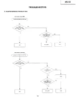
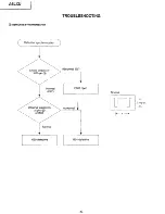
Page 36: ...AGLXU TROUBLESHOOTING NO VERTlCAt DEFLECTION OR V SIZE IS DISTORTED ov 1 Normal 26V 1620 D721 R730 defective F601 open 25V ov Normal ov 12V DC 50V peak 4 36 ...

Page 37: ...BLESHOOTING NO SOUND WHEN SURROUND OFF OV or lower 23V Defective Audio Power Supply line input at pins and I 1402 defective IA03 defective No I i IYOI defective No I I Ul 01 Front End Circuits defective 37 ...

Page 38: ...AGLXU TROUBLESHOOTING NO SOUND NO AUDIO POWER Check SVcc2 F L935 defective CHANNEL DISPLAY IS NOT DONE waveform of 1001 Abnormal Normal waveform of 1001 1007 and peripheral parts defective Normal 38 ...

Page 39: ...I A6LXU TROUBLESHOOTING CHANNEL SELECTION IS NOT DONE Abnormal Normal Channel Display vary Abnormal Normal NO YES f UIOI QIOI Q102 Qi 05 defective 39 ...

Page 40: ...HOOTING DOES NOT OPERATE BY REMOTE CONTROL Abnormal I Normal channel channel UP DOWN UP DOWN Operate by the TV set Operate by the TV set Does the power turn NO YES 4 4 voltage of HMO1 pin I ov ov b b Normal Abnormal 40 ...

Page 41: ... EL 47UF M 25V CA39 0800041 R EL 47UF M 16V CSFl 0800059R EL 220UF M 25V CA40 0800015R EL lOUF M 16V CSF6 0800042R EL 47UF M 25V CA41 0800015R EL 1OUF M 16V CSF7 0800042R EL 47UF M 25V CA50 0284634R EL 4 7U M 50V CSF8 0800051 R EL l OOUF M 25V CA51 0800009R EL 4 7UF M 25V CSF9 0800083F EL lOOOUF M 25V CA52 0284634R EL 4 7UF M 50V CSG3 0880057R PF 0 1 UF KEB 50V CA53 0800015R EL lOUF M 16V CSG4 088...

Page 42: ...oo7 0284623R EL 1 UF SME BP 50V CS80 0800015R EL lOUF M 16V COO8 0284623R EL IUF SME BP 50V CS81 0800049R EL lOOUF M 16V coo9 0284623R EL 1UF SME BP 50V CS82 0800015R EL IOUF M 16V co1 0 0284623R EL I UF SME BP 50V CS83 0284623R EL 1UF SME BP 50V co11 0800003R EL l OUF M 5OV CS84 0880055R PF O O68UF KEB 50V co12 0800003R EL l OUF M 50V CS85 0800049R EL lOOUF M 16V co13 0284623R EL 1UF SME BP 50V C...

Page 43: ...7R EL 3 3UF M 50V c505 0890116R CD 15PF J CH 50V c314 0800003R EL 1 OUF M 50V C506 0880044R PF 0 01 UF KEB 50V c315 0800049R EL lOOUF M 16V c507 0244171 R CD 0 01 UF Z F 50V TAPE C316 0244171 R CD 0 01 UF Z F 50V TAPE C508 0244171 R CD 0 01 UF Z F 50V TAPE c317 0800058R EL 220UF M 16V c509 0244171 R CD 0 01 UF Z F 50V TAPE C318 0800003R EL 1 OUF M 50V c510 0244171 R CD 0 01 UF Z F 50V TAPE c319 02...

Page 44: ... CE04W2E33 DA09 2348212M DI MTZ J15BTA c739 0255507F EL 22UF MB 1GOV KME DA10 2348212M DI MTZ Jl SBTA c740 0255524N EL 4 7MF M 250V DA11 2398611 M DI 1SS254 TAPE 35V SI 4NSEC c741 0276717R PP O lUF J 50V TF TYP E DA1 2 2398611 M DI IS5254 TAPE 35V SI 4NSEC A 754 0800003R EL 1 OUF M 50V DA70 2339889M ZD HZS12 C3 0 005A c755 0890086R CD 820PF K 50V DA71 2339889M ZD HZS12 C3 0 005A c757 0800005R EL 2...

Page 45: ...4 TAPE 35V SI 4NSEC D304 2398611 M DI 1SS254 TAPE 35V SI 4NSEC D805 2398611 M DI 188254 TAPE 35V SI 4NSEC D305 2398611 M DI lSS254 TAPE 35V Sl4NSEC D806 2398611 M DI 155254 TAPE 35V SI 4NSEC D306 2398611M DI 155254 TAPE 35V SI 4NSEC D820 2339601M ZD HZS 2 TAPE ALL SI 400MW D307 2398611 M DI 1 SS254 TAPE 35V Sl4NSEC D821 2339601M ZD HZS 2 TAPE ALL SI 400MW D308 2398611 M DI 1 SS254 TAPE 35V Sl4NSEC...

Page 46: ...3468M FERRITE BEADS CORE LEAD 0 8MH I501 2020324 ANALOG MONOLITHIC IC YATO16H L860 2123468M FERRITE BEADS CORE LEAD 0 8MH I502 CP02781 M62399P L861 2123468M FERRITE BEADS CORE LEAD 0 8MH 16HO 2362601 IC HA1 7458PS L862 2123468M FERRITE BEADS CORE LEAD 0 8MH A I620 2003541 IC LA7838 L863 2123468M FERRITE BEADS CORE LEAD 0 8MH dhl7HO 2000521 IC PC713F6 ALgo1 2169462 LINE FILTER COIL FX 7355 60 1702 ...

Page 47: ... TRS 2SC458 B TiX TZ SI 230MHZ QY51 2320591M TRS 2SC458 B TUC TZ SI 230MHZ Q856 2320637M TRS 2SA673 C 26TUD 26TZ SI 80MHZ QY52 2320637M TRS 2SA673 C 26TUD 26TZ SI 80MHZ Q857 2315491 TRS 2SC4544 QY53 2320591 M TRS 2SC458 B TZ C TZ SI 230MHZ Q858 2320591 M TRS 2SC458 B TZ C TZ SI 230MHZ QOOl 2320591M TRS 2SC458 B TZ C TZ Sl230MHZ Q859 2320637M TRS 2SA673 C 26TZ D 26TZ SI 80MHZ Q002 2327772M TRS 2SC3...

Page 48: ...6W 5 6K JB RA60 0700041 M CF l l 6W 1 OK JB RSC6 0700051 M CF 1 16W 5 6K JB RA61 0700067M CF l l 6W 1OOK JB RSC8 0700045M CF 1 16W 2 2K JB RA62 0700041 M CF l l 6W 1 OK JB RSC9 0700045M CF l l 6W 2 2K JB RA63 0700041 M CF l l 6W 1 OK JB RSE2 0700054M CF 1 16W IOK JB RA64 0100123M CF 1 8W 270K JB RSE3 0700054M CF l l 6W 1 OK JB RA65 0100123M CF 1 8W 270K JB RSE4 0700036M CF 1 16W 470 JB RA66 010012...

Page 49: ... J RS29 0700067M CF 1I1 6W 1OOK JB RV33 0113686M CF 1 2W 2 7 J RS30 0700067M CF 1 16W lOOK JB RV34 0113686M CF 1 2W 2 7 J RS39 0700054M CF 1 16W lOK JB RV35 01102298 MF 220 JS RS42 0700041 M CF l l 6W 1 OK JB RV36 0110135S MF 390 JS RS43 0700027M CF 1 16W lOO JB RV37 0110132s MF 300 JS RS46 0700027M CF 1 16W 100 JB RV38 0700047M CF l l6W 33K JB RS47 0700041 M CF l l 6W 1 OK JB RV39 0700051 M CF l ...

Page 50: ...100038M CF 1 8W 75 JB R006 0700063M CF l l 6W 47K JB RY74 0100101 M CF 1 8W 33K JB R008 0700063M CF 1 16W 47K JB RY77 0100123M CF 1 8W 270K JB R009 0700054M CF 1 16W IOK JB RY78 Ot00123M CF 1 8W 270K JB ROlO 0700054M CF 1 16W lOK JB ROA3 0700058M CF 1 16W 22K JB Roll 0700041 M CF 1 16W 1 OK JB ROA5 0700027M CF 1 16W 100 JB R012 0700064M CF 1 16W 56K JB ROA6 0700037M CF 1 16W 560 JB R014 0700054M C...

Page 51: ...RO84 0700041 M CF 1 16W 1 OK J B R323 0700054M CF 1 16W lOK JB R085 0700041 M CF 1 16W l OK JB R324 0700041 M CF l l 6W 1 OKJB R086 0700041 M CF 1 16W 1 OK JB R325 0700048M CF l l 6W 3 9K JB R087 0700041 M CF l l 6W 1 OK JB R326 0700054M CF l l 6W IOK JB R088 0700041 M CF l l 6W 1 OK JB R327 0700054M CF 1 16W lOK JB R089 0700027M CF 1 16W lOO JB R328 0700065M CF 1 16W 68KJB R090 0700041 M CF l l 6...

Page 52: ...M CF 1 16W 1 OK JB R5C4 0700035M CF 1 16W 390 JB R543 0100125M CF 1 8W 330K JB R5C5 0150133 VR RV06 500 B R544 0700041M CF 1 16W l OKJB R5C6 0700035M CF l l 6W 390 JB R545 0700041 M CF l l 6W 1 OK JB R5C7 0150133 VR RV06 500 B R546 0100047M CF 1 8W 180 JB R5C8 0700035M CF 1 16W 390 JB R547 0700041 M CF l l 6W 1 OK JB R5C9 0100041 M CF I 8W lOO JB R548 0700041 M CF l l 6W 1 OK JB R5El 0100041M CF 1...

Page 53: ...50302 VR RV6 2K B V R7H1 0700058M CF l l 6W 22K J5 R867 0700038M CF 1 16W 680 JB R7H2 0700064M CF 1 16W 56K JB R868 0150302 VR RV6 2K 5 V R7H3 0700066M CF 1 16W 82K J5 R869 0700038M CF 1 16W 680 J5 R7H4 0700064M CF 1 16W 56K JB R870 0150302 VR RV6 2K 5 V R7H5 0700057M CF 1 16W 18K JB R871 0700038M CF 1 16W 680 JB R7H6 0150115U VR RV6 POK B U R874 0700054M CF 1 16W lOK J5 R7H7 0700061 M CF 1 I 6W 3...

Page 54: ...63328 2J MINI CONN W WIRE AT701 2274353 TRANS H DRIVE EMUT 2974027s CONN SEH02C B1007A181 a T702 BWOO571 HFL1735LD ENH2 EF04011 CONN 05C C5RO 461 2 4N T901 2124361 DC NOISE FILTER ENH3 EF0292l CO 06C CZR5 430 AT902 BTOO462 COIL PT EE35Fll U ENS1 EF03012 CO 5C C2R5 470 RED T903 2124362 DC NOISE FILTER EP37 29739768 CONN SSEH12C C1007A L 390 AT991 2215911 POWER TRANSFORMER EP46 EF04021 CONN 14C C2R5...

Page 55: ...2902264 PLUG PIN SUB MINI 5P N112 3785502 V LOCK 11 5 P31 2661751 2P PLUG PIN WITH BASE N201 QR06081 35UX85B 511 INSTRUCTION BOOK P901 2782611 CENTER PIN N202 H461705 WARRANTY CARD E 20 35V P902 2782611 CENTER PIN N209 H461901 HITACHI EXT SVC CARD Asp451 2735335 MGZ SDX SP AS Y A3 N301 4712247 CUSTOMER REGISTRATION CARD ASP452 2735335 MGZ SDX SP AS Y A3 N401 QNO1009 SERVICEMAN WARNING AVI DE00881 ...

Page 56: ......

Page 57: ...A6LXU BLOCK DIAGRAM ...

Page 58: ......

Page 59: ......

Page 60: ......

Page 61: ......

Page 62: ......

Page 63: ......

Page 64: ......

Page 65: ......

Page 66: ......

Page 67: ......

Page 68: ......

Page 69: ......

Page 70: ......

Page 71: ......

Page 72: ......

Page 73: ......

Page 74: ......

Page 75: ......

Page 76: ......

Page 77: ......

Page 78: ......

Page 79: ......

Reviews: