background image

Summary of Contents for 46UX50B

Page 1: ...the service technician read the Safety Precaution and Product Safety Notices in this service manual SAFETY NOTICE USE ISOLATION TRANSFORMER WHEN SERVICING Components having special safety characteristics are identified by a h on the schematics and on the parts list in this Service Data and its supplements and bulletins Before servicing the chassis it is important that the service technician read a...

Page 2: ...and safely repair complex products such as those covered by this manual Improperly performed repairs can adversely affect the safety and reliability of the product and may void warranty If you are not qualified to perform the repair of this product properly and safely you should not risk trying to do so and refer the repair to a qualified service technician WARNING Lead in solder used in this prod...

Page 3: ...th the instrument AC switch in the off position Leakage Current Hot Check With the instrument completely reassembled plug the AC line cord directly into a 120V AC outlet Do not use an isolation transformer during this test Use a leakage current tester or a metering system that complies with American National Standards Institute ANSI Cl 01 O Leakage Current for Appliances and Underwriters Laborator...

Page 4: ...Shield Plate A Shield Plate C Fig 1 Detailing X radiation Shield 4 ...

Page 5: ...y These chassis can be safely serviced only with an isolation transformer inserted in the power line between the receiver and the AC power source for both personnel and test equipment protection c Some TV receiver chassis have a secondary ground system in addition to the main chassis ground This secondary ground system is not isolated from the AC power line The two ground systems are electrically ...

Page 6: ...by this service data might be equipped 7 Do not apply AC power to this instrument and or any of its electrical assemblies unless all solid state device heat sinks are correctly installed 8 Always connect the test instrument ground lead to the appropriate instrument chassis ground before connecting the test instrument positive lead Always remove the test instrument ground lead last 9 Use with this ...

Page 7: ...ith boards using the familiar round hole use the standard technique as outlined in paragraphs 5 and 6 above 2 Draw away the melted solder with an anti static suction type solder removal device or with solder braid before removing the IC Replacement 1 Carefully insert the replacement IC in the circuit board 2 Carefully bend each IC lead against the circuit foil pad and solder it 3 Clean the soldere...

Page 8: ... of a small gauge jumper wire and carefully crimp it around the IC pin Solder the IC connection At Other Connections Use the following technique to repair defective copper pattern at connections other than IC Pins This technique involves the installation of a jumper wire on the component side of the circuit board Insulated Jumper Wire 1 Remove the defective copper pattern with a sharp knife Remove...

Page 9: ...ponent end caps or terminals 2 Without pulling up carefully twist the component with tweezers to break the adhesive 3 Do not reuse removed leadless or chip components since they are subject to stress fracture during removal Chip Component Installation 1 Put a small amount of solder on the board soldering pads 2 Hold the chip component against the soldering pads with tweezers or with a miniature al...

Page 10: ... and turn on TV 5 Turn off set immediately after checking circuit operation Confirm test pattern on CRT is a usable picture then slowly adjust jig until the picture disappears and TV shuts down 6 Unplug set for one minute to reset shutdown circuit Remove jig and voltmeter Chassis ground High impedance H V meter B line El T9Od c929 I FBT T702 Disconnect the pin of 1905 from B line Connect jig 15kQ ...

Page 11: ...t Power Front 10watts rms per channel 8 ohm impedence Maxoutput 12 watts Rear 7 5 watts per channel 8 ohm impedence Max output 10 watts Center 7 5 watts Max output IO watts Anode Voltage 30 0 kV Zero BeamCurrent Brightness 235 cd m2 46UX50B 51K 200 cd m2 50UX52B 53K 140 cd m2 60UX54B 55K white screen Speakers 2 Woofers 5 inch 12 mm round 2 Tweeters 2 inch 5 mm round Centerspeaker 4 inch 10 mm roun...

Page 12: ...o Output Power Front 15 watts rms per channel 8 ohm impedence Max output 18watts Rear 7 5 watts per channel 8 ohm impedence Max output 10 watts Center 15 watts Maxoutput 18 watts Anode Voltage 31 5 kV Zero BeamCurrent Brightness 250 cd m2 50SBX70B 170cd m2 6OSBX72B 125 cd m2 7OSBX74B white screen Speakers 2 Woofers 5 inch 12 mm round 2 Tweeters 2 inch 5 mm round 2 Centerspeaker 4 inch 10 mm round ...

Page 13: ...TO DIGITAL CONVERGENCE VIDEO 3 INPUT REAR SPEAKER TERMINALS Fig 3 Control Panel REAR SPEAKER TERMINALS i y 9 J ANT A 7 L TO 1 CONVERTER VtDEO 1 VIDEO VIDEO SUB WOOFER OUTPUT A VARIABLE AUDIO OUTPUT ANTENNA INPUTS OUTPUT INPUTS 1 AND2 Fig 4 Rear Connections Panel VARIABLE TRANSMIlTER AUDIO OUTPUT 13 ...

Page 14: ...DEO 3 INPUT CONVERGENCE Fig 3 Control Panel REAR SPEAKER TERMINALS s zz REAR SPEAKER TERMINALS Y I ANT A J l L 7 TO ER SUB WOOFER OUTPUT INPUT 1 INPUT 2 MO ORWI EsS A D C TOHII L 1 3 I f k I VARIABLE I V OUTbJT AUDIO OUTPUT ANTENNA INPUTS OUTPUT INPUTS VARIABLE 1 AND2 TRANSMITTER Fig 4 Rear Connections Panel AUDIO OUTPUT 14 ...

Page 15: ...st the overall picture brightness I COLOR Use this function to adjust the level of color in the picture TINT Use this function to adjust flesh tones so they appear natural I SHARPNESS Use this function to adjust the amount of fine detail in the picture m conditions When RESET is selected press CURSOR to return video adjustments to factory preset Press the front panel MAGIC FOCUS button momentarily...

Page 16: ...aphic Eq 81 Bass Treble INOTE If BASS is selected you are adjusting BASS The additional menu items TREBLE and BALANCE can be selected and adjusted in the same manner I I BASS I This function controls the low frequency audio to all speakers TREBLE This function controls the high frequency audio to all speakers This function will control the left to right balance of the TV internal speakers the AUDI...

Page 17: ...rom the case Wing L Position L Position Fig 6 During Insertion 1 Please refer to direction for insertion as shown in Fig B L position Insert connector until CLICK sound is heard 2 Make sure the connector is pressed right in so that it has a good contact with the spring 3 Confirm the contact by pulling the connector slightly Don t pull hard because it may damage the connector 4 Cover the high volta...

Page 18: ... Hall Surround Monaural Check 2 5 7 Dolby Surround Check 2 5 8 Dolby Surround Monaural Check Raster Inclination Adjustment Deflection Yoke Raster Position Adjustment Vertical Size Adjustment R630 Horizontal Size Adjustment R603 Beam Alignment BeamShape Adjustment Static Focus Adjustment Blue Defocus Adjustment Digital Convergence Adjustment 2 l 4 l Phase Adjustment service mode 2 l 4 2 Raster Posi...

Page 19: ...ntrols to center 3 Set the Al to OFF Adjustment procedure I Check that between the color bars there are line dots every second color bar as shown in the drawing 1 3 Check and line dots I 1 AP73 i AP74 1 0A Dots x Dots None I 0 B None None Sub picture position adjustment Adjustment preparation 1 Select signal on main picture 2 Video settings have to be at normal condition Adjustment procedure Press...

Page 20: ...s not the same observe the vertical bright line at the center of the screen and set to the position where red chromatic aberration slightly appears inside and blue outside reference value 1 3mm within the cross hatch pitches specified in next table When the red chromatic aberration appearing at both sides of the bright line is not equal observe the side with larger chromatic aberration when adjust...

Page 21: ...een Push the button again to return to Normal side Press MENU button to exit VIDEO CHROMA ADJUST 5 6 7 03 91 NOTE Select the input signal for high brightness Video level 0 715Vpp Adjust the high brightness white balance using the drive adjustment VRs red green Select the signal for low brightness Video level 0 3OOVpp Adjust the low brightness white balance using the screen adjustment VRs red green...

Page 22: ...and REAR to around their centers l Set the BASS TREBLE and BALANCE to TYP Note Front waveform Front speaker output of the set Rear waveform Rear speaker output of the set Center waveform Center speaker output of the set 2 51 Surround off check Adjustment procedure 1 Set to SURROUND OFF and check that the waveform shown below is obtained input signal 0 and FRONT SkHz R 400Hz Note The rear and cente...

Page 23: ...ocedure 1 Set to SURROUND DOLBY l a L R Check that the following waveforms are obtained Input Signal and Front 400 Hz is superimposed on 5kHz Rear R and L are the same signal and 400Hz is superimposed on 5kHz FRONT REAR Note MODE PRO LOGIC NORMAL 2 5 6 Dolby surround monaural check Adjustment procedure l Check that the following waveforms are obtained Input signal only l Front Almost no output fro...

Page 24: ...screen NOTES 1 If internal cross hatch does not appear after clearing RAM data press service switch again 2 To restore old RAM data turn TV off and on 2 8 Vertical size adjustment R630 Adjustment preparation I 5 6 7 The set can face east or west Input the single cross test signal Set video conditions to factory reset The lens focus adjustment should have been completed The electric focus should ha...

Page 25: ...city shocks mav be caused if thev are not short circuited Adjustment procedure I Green G tube beam alignment adjustment Short circuit 2P subminiature connector plug pins of Red R and Blue B on the CPT boards and project only Green G tube 2 Put Green G tube beam alignment magnet to the cancel state as shown below 3 Turn the Green G static focus Focus Pack counterclockwise all the way and make sure ...

Page 26: ...green CPT PW Bs to display only the blue beam 3 Turn the B Focus VR Focus Pack fully clockwise 4 Measure the brightness at the center of the screen and turn the B FOCUS VR Focus Pack counterclockwise to adjust the brightness of blue as shown in Table 5 After the adjustment is completed if blue exceeds the specification turn and adjust focus so that the sticking out part of blue satisfies the speci...

Page 27: ...4 Press ENTER 5 times to display external signal 5 Identify center of active video then press ENTER 5 times to return to internal cross hatch 6 Press HELP phase acij and use 2 4 5 and 6 to position internal cross hatch center on active video center identified in step 5 7 Press HELP to exit PHASE mode ACTlVE VIDEO CENTER FROM STEP 5 BEFORE USECURSOR KEYSTO MOVE DOllEDLINES BETWEENBENT LINES FIRST T...

Page 28: ...E button again to write displayed data to ROM 7 DATA WRITE TO ROM will take approximately 20 seconds and no picture will be displayed 8 Green dots will be displayed when operation is complete 9 Press MUTE to return to convergence pattern then confirm again convergence is acceptable 10 Press MOVE ROM WRITE mode then press PIP CH to initialize sensor data positions Notes 1 Display only green for eas...

Page 29: ...ING MAGNET FOR RED PRT 2 CENTERlNG MAGNET FOR GREEN PRT 3 CENTERlNG MAGNET FOR BLUE PRT 4 4 POLE MAGNET FOR 8EAM FORM ADJUSTMENT 5 BEAM ALIGNMENT MAGNET 6 DIGITAL CONVERGENCE MODULE On Power Deflection board 7 FOCUS PACK TOP ADJUSTMENTS FOR SCREEN BOTTOM FOR FOCUS 29 ...

Page 30: ...Red p W 8 SIGNALSUB VM rUNEI 1 with MTS Main kture p W 8 SDYIC AP74 ONLY 1 u301 PIP P W B 0 325 SK01 SERVICEONLYbutton CONV ADJ ml T E4 R630 R603 V SIZE l Q 10965 H SIZE ss9v FLY 10 SD3 rnD977 AUDlO22V IXID912 PROTECTtRED q JD947 AUDlO32V IXISERVICELED ...

Page 31: ...BX74B GREEN 0 0 GN D RED DqlVE RED 0 0 FOCUS PACK UFPK 0 0 o Screen Adj VR R G B 0 0 o Focus Adj VR R G B REMOTE CONTROL LIGHT RECEIVING PACK POWER VOL DOWN CH DOWN s VLR MENU INPUT EXIT VOL UP CH UP AUTO DIMMER CONTROL DIGICON LIGHT RECEIVER MAGIC FOCUS AUTO DtGlCON MAGIC FOCUS CH CH 31 ...

Page 32: ... 2V line 1910 Q926 1001 I102 IYOl IYO2 HMO1 etc I No I u v 1Find which LED s is going to dark or OFF Other LED s are going to OFF little bit later same time c D940 B 1 Check B 12OV line E994 Q777 T702 C701 etc etc I D966 27V Check 27V line E995 Q902 IK04 IK05 etc 32 D967 23V D947 32V Check Check 23V line Audio32V E996 1909 line IK04 IK05 E992 E997 etc 1401 etc D977 22V Check Audio22V line E993 E99...

Page 33: ...1901 D911 D910 D969 Replace E991 Does raster Does raster Is base Yes Yes 1 voltage of Q701 normal Q701 normal v Check 1905 1903 1902 Check 1905 1903 1902 b Q914 Q913 Q912 Q914 Q913 Q912 Q909 T90l etc Q909 T90l etc Yes Yes About AC 0 3V About AC 0 3V No No No No m I e E991 33 ...

Page 34: ...cture Normal Abnormal Q517 Q516 Q515 Does on screen No pin k v 2v Yes w f 1VP P I IV r v s v normal at oin GJ of Normal Abnormal r l Q512 1 Normal I l 1x01 1x02 3 line Comb U I Ul 01 Front end IYOl Ql 01 I 34 ...

Page 35: ...3 Reception impossible with snow noise ANT A YtEi NO No ANT B 1 U101 r I Yes Yes Yes 1106 D117 1912 I 35 ...

Page 36: ...4 Defective synchronization Abnormal OV t Normal 26 1 Normal t Abnormal Normal 36 ...

Page 37: ...orrect color When normal I 1 No f 0 6 Vp p 7 1X01 1X02 etc 3 Line Comb UX only U301 3D Comb SX only retrace line appear with signal color Red does not appear Q861 Q862 D861 PRT R Blue does not appear Q801 Q802 D801 PRT B 37 ...

Page 38: ...r 32V E992 32V Power Supply Yes No IS05 1 Check the 12C bus SCL SDA 2 Check IGOl GEQ IC Yes No IS01 1 Check the Bus Line clock data enable 2 Check IS02 Yes No IS12 1 Check the pin of IS12 Yes No v UlOl I IYOl 1 Check the 12C bus SCL3 SDA3 38 ...

Page 39: ...CU 1 Darken Outside light 2 Placing of sensor 3 Is pattern hitting sensor x X 4 Check connection and solder bridge of sensor 5 Replace sensor 6 Replace sensor P W B 7 Sensor Connector check 8 Replace DCU X c 9 Adjustment check H V size centering 3 2 A D Level Same as Error Code 2 X X 4 Over Flow 1 Check the placement of sensor X X 2 Adjustment check H V size centering 3 Conv amp gain check 1 check...

Page 40: ...998 E993 Audio Rectifier 23 D915 Rectifier 31 D916 D967 23V Regulator Conv w E996 12 1909 12v 7000 D964 Regulator A 12 1910 D946 120 D929 Volt Control B 1905 Standby Q907 TV ON OFF Mode Switch Q905 6 Q908 Regulator TV Signal TV 5 1913 Circuit TV 5V Da9 5 v B I E W UY4U flf Ml qn 6B 8 bU HZ 1 TV Main ON OFF PROTECTION CIRCUIT BLOCK DIAGRAM ...

Page 41: ......

Page 42: ......

Page 43: ......

Page 44: ......

Page 45: ......

Page 46: ......

Page 47: ......

Page 48: ......

Page 49: ......

Page 50: ......

Page 51: ......

Page 52: ......

Page 53: ......

Page 54: ......

Page 55: ......

Page 56: ......

Page 57: ......

Page 58: ......

Page 59: ......

Page 60: ......

Page 61: ......

Page 62: ......

Page 63: ......

Page 64: ......

Page 65: ......

Page 66: ......

Page 67: ......

Page 68: ...0 0 6 _ ...

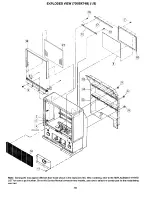
Page 69: ...pear different than those shown in the exploded view When ordering refer to the REPLACEMENT PARTS LIST for correct part number Since this Service Manual covers several models use care to select the correct part for the model being serviced 69 ...

Page 70: ...pear different than those shown in the exploded view When ordering refer to the REPLACEMENT PARTS LIST for correct part number Since this Service Manual covers several models use care to select the correct part for the model being serviced 70 ...

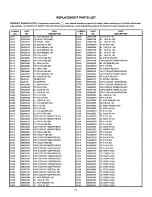
Page 71: ...800003R 0800003R 0800003R 0800003R 0800015R 0800015R 0800015R 0800015R 0800015R 0800015R 0800015R 0800015R 0800015R 0800015R 0800041 R 0800041 R 0800015R 0800015R 0800015R 0800015R AN00637R 0800015R CAPACITORS EL l OUF M 5OV EL l OUF M 5OV EL l OUF M 5OV EL l OUF M 5OV EL l OUF M 5OV EL l OUF M 5OV EL l OUF M 5OV EL l OUF M 5OV EL lOUF M 16V EL lOUF M 16V EL lOUF M 16V EL lOUF M 16V EL lOUF M 16V ...

Page 72: ...F KEB 50V CAP2125CHIP 39000PFKB 50V CAP 2125CHIP 3300PFKB 50V CAP 2125CHIP 3300PFKB 50V CAP2125CHIP 39000PFKB 50V CAP 2125CHIP 18000PFKB 25V CAP 2125CHIP 1200PFKB SOV CAP 2125CHIP 1200PFKB 50V CAP 2125CHIP 18000PFKB 25V CAP 2125CHIP 8200PFKB 50V CAP2125CHIP 560PFJSL 50V CAP2125CHIP 560PFJSL 50V CAP 2125CHIP 8200PFKB 50V EL IOUF SME BP 16V EL IOUF M 16V EL IOUF SME BP 16V EL IOUF M 16V CG39 CG40 CG...

Page 73: ...HIP 68OPF J SL 5OVTA EL IOUF M 16V EL IOUF M 16V EL IOUF M 16V PF 0 47UF J 5OV EL 47UF M 16V PF 0 1 UF 5OV PF 0 1 UF 5OV EL 0 47UF M 50V SME EL 4 7UF M 5OV cs15 CS16 cs17 CS18 cs19 cs20 cs21 cs22 CS23 CS24 CS25 CS26 CS27 CS28 cs29 cs30 cs31 CS32 cs33 cs34 cs35 CS36 cs37 CS38 cs39 cs40 cs41 CS42 cs43 cs44 cs45 CS46 cs47 CS48 cs49 cs51 CS52 cs53 cs54 cs55 CS56 cs57 CS58 cs59 CS60 CS61 CS62 CS64 CS65...

Page 74: ...OUF M 25V EL lOOOUF M 25V PF 0 01 UF 50V PF 0 01 UF 50V EL IOUF SME BP 16V EL IOUF M 16V EL l OUF M 50V EL 47UF M 16V AP73 ONLY CD 22PF J 50V AP73 ONLY CD IOPF 50V AP73 ONLY CD 18PF J SL 50V AP73 ONLY CX28 cx29 cx30 cx31 CX32 cx33 cx34 cx35 CX36 cx37 CX38 cx39 cx40 cx41 CX42 cx45 CX46 cx47 CX48 cx49 cx50 CX52 cx53 cx54 CYOl CYO2 CYO3 CYO4 CYO5 CY06 CYO7 cYo8 CYO9 CYI 0 CYII CY12 CY13 CYl4 CY15 CY1...

Page 75: ... 0 01 UF 50V CAP21 25CHIP 47000PFKB 50V EL S LEAD 1500UF M XV IDV PF 0 1 UF 50V EL S LEAD 1200UF M LXV 16V EL t OUF M 50V PF O lUF 50V CAP2125CHIP 12OPFJSL 50V CAP21 25CH IP 47000PFKB 5OV EL IOOUF M 6 3V EL IOOUF M 6 3V CAP21 25CHI P 47000PFKB 50V CD 47PF 500V Cl 28 Cl29 Cl 29 Cl30 Cl31 Cl32 Cl36 c137 Cl38 Cl39 Cl40 Cl41 c142 CICI c301 C302 c3A2 C3A3 c401 C402 c403 c404 c405 C406 c407 C408 c409 c4...

Page 76: ...V PF 0 1 UF 50V PF 0 1 UF 50V EL 4 0UF M 16V PF 0 022UF 50V PF 0 1 UF 50V EL 2 2UF M 50V PF O lUF 50V PFO lUF5OV PFO lUF5OV CAP2125CHIP IOOOOPFKB 50V CAP2125CHIP IOOOOPFKB 50V EL 220UF M 16V PF 0 1 UF 50V EL IOOUF M 16V PF 0 1 UF 50V C601 C602 C603 C604 C605 C606 C607 C608 C609 C610 C611 C612 C613 C614 C615 C616 C617 C619 C620 C621 C622 C632 C633 c701 C702 c703 c704 c705 C706 A c707 A c707 B C708 ...

Page 77: ...00UF M XV 35V EL S LEAD 1200UF M XV 35V EL390UF M 16OV EL S LEAD 1200UF M XV 16V EL470UF M 16V EL 470UF M 35V EL S LEAD 1500UF M XV 16V EL lOOUF M 35V EL470UF M I6V PF 0 22UF KEB 50V EL 47tiF M SMG 16V EL 1 OUF M SMG 50V EL IOUF M SMG 16V EL S LEAD 2200UF M XV 1OV 952 0800291 R 954 080029 I R 955 AN00637R 956 AN00637R 957 0800299R C958 AJ00157R 1 c959 AJOOq63R 961 AL00796S 962 0800326R 963 0800294...

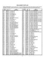
Page 78: ...TAfl SS27OTA DI lSS254TAJlSS27OTA DI 1 SS254TA l SS27OTA DI 1 SS254TAll SS27OTA DI 1 SS254TAIl SS27OTA DI 1 SS254TAll SS27OTA DI lSS254TA lSS27OTA ZD MTZJ 6 2C TA ZD MTZJS ZC TA ZD Ml ZJ 6 2C TA ZD MTZJ 6 2C TA ZD MTZJS ZC TA ZD MTZJ 6 2C TA ZD MTZJ 6 2C TA ZD MTZJ 6 2C TA ZD DI HZ 9 Cl SI 500MW DI MTZ J 9 1ATA DI MTZ J 9 1ATA DI MTZ J 9 1ATA DI MTZ J 9 1ATA DL35 DL36 DL37 DMOI DMOI DM02 DM02 DM03...

Page 79: ... D713 CH00901 M D1 RGP02 15E 1500V 20A Dl14 2348212M DI MI Z Jl5BTA AP73 ONLY D714 CH00901 M DI RGP02 15E 1500V 20A Dl15 2348052M DI MTZ J3 3BTA AP73 ONLY 0715 2348431 M DI RMPGOGD D116 2331815M ZD HZ7 B2 D716 2348203M ZD DI MlZJ 13C TA D117 2335991 M ZD HZ T33 02 TP D717 2339612M ZD HZS 3 TA BLL SI 200MA Dl18 2335991 M ZD HZ T33 02 TP D718 2344041 M Dl lSS254TAIl SS27OTA D301 2334324M ZD DI RD36E...

Page 80: ...AJ l SS27OTA DI 1SS254TAJl SS27OTA DI 1SS254TA l SS27OTA LIGHT EMITTING DI SIZ 381C 06 Tl LIGHT EMITTING DI SLZ 381C 06 Tl DI lSS254TAllSS27OTA ZD MlZ J4 7BTA DI lSS254TA lSS27OTA DI 1SS254TA l SS27OTA ZD DI MTZJ 15C TA DI 1SS254TAll SS27OTA DI 1SS254TAll SS27OTA DI lSS254TAflSS27OTA DI lSS254TAflSS27OTA DI lSS254TAll SS27OTA DI lSS254TA l SS27OTA LIGHT EMI ITING DI SLZ 381C 06 Tl LIGHT EMITTING D...

Page 81: ...O2 2123763R LSO3 2123763R LSO5 2123763R LS06 2123763R Lx01 2123105M LX05 2123763R LX06 2123763R LX07 2123763R LX08 2123763R Lx09 2123763R Lx10 2123763R Lx11 2123109M LYOI 2123781 R LYO3 2123763R LYO4 2123763R LYO5 2123763R LOO2 2123781 R LOO3 2123781R LO04 2123763R LIOI 2123763R L102 2123763R L103 2123781R L104 2123781 R L105 2123781R L106 2123781R L107 2123781 R LllO 2123781 R Llll 2123781 R L112...

Page 82: ...5248 160V QE12 QFOI QF03 QF04 QF05 QF06 QF07 QF08 QF09 QFIO QFII QF12 QF13 QF14 QF15 QF16 QF17 QKOI QK02 QK03 OK04 QK06 QK07 QK08 QLIO QLll QL12 QL13 QL14 QL15 QL16 QL17 QMOI QMOI QM02 QM02 QM02 QM03 QM03 QM04 QM04 QNOI QN02 QN03 QN04 QN05 QN06 QSOI QS18 QS20 QS21 QXOI Qxo2 Qxo5 QX06 2320637M 2320637M 2320663M 2320637M 2320663M 2315341 F 2315341F 2315341F 2320591 M 2320637M 2320663M 2320591 M 2320...

Page 83: ...KQ R TR CHIP 2SC2412KQ R TR CHIP 2SC2412KQ R TR CHIP 2SC2412KQIR TR CHlP 2SC2412KQ R TR CHlP 2SC2412KQIR TR CHIP 2SC2412KGUR TR 2SA673 SI 80MHZ AP73 ONLY TR 2SA673 SI 80MHZ AP73 ONLY TR CHIP 2SC2412KQ R ZSA1037KTj 46Q R TR CHIP 2SC2412KQ R AP74 ONLY TR CHIP 2SC2412KQ R AP74 ONLY Q402 Q403 Q404 Q405 Q406 Q407 Q500 Q501 Q502 Q503 Q504 Q505 Q506 Q509 Q510 Q512 Q5l3 Q514 Q515 Q5l6 Q517 Q519 Q601 Q602 ...

Page 84: ...C7 0700041 M CF 1 16W l OK JB RA21 01959OOR RES 2125 CHIP 1 16W IKJ RAC8 0195950R RES 2125 CHIP 1 16W IOOKJ RA22 0195887R RES 2125 CHIP 1 16W 330J RAC9 0195939R RMC73S 2A393JR RA23 0195883R RES 2125 CHIP 1 16W 220J RADl 0195900R RES 2125 CHIP 1 16W 1KJ RA24 0195939R RMC73S2A393JR RAD2 0195925R RES 2125 CHIP 1 16W IOKJ RA25 0195925R RES 2125 CHIP 1 16W 1OKJ RAD3 0195900R RES 2125 CHIP 1 16W IKJ RA2...

Page 85: ... 1 16W IOOK J5 CF 1 16W 2 7K JB CF 1 2W 470 JB CF 1 I 6W 33K JB CF 1 16W 470 58 CF 1 16W IOOK JB CF 1 16W lOK JB CF 1 8W 1K JB CF 1 16P 82 JB AP74 ONLY CF 1 16W IOO JB AP73 ONLY CF SRD1 2P B IO J CF li8W 82 JB CF SRD l 4 PF 1 5K J CF 1 4W 1 2K JB CF l 4 PB 68K J CF l 4 PB 68K J CF SRDl ZP B 12K J CF 1 8W 82 JB CF 1 8W 1 5K JB CF 1 8W 1 2K JB CF SRD1 2P B 43 J RE34 RE35 RE36 RE37 RE38 RE39 RE40 RE4...

Page 86: ...IIIG 7 5K J RG54 0195900R RES 2125 CHIP 1 16W 1KJ AP74 ONLY RG54 0700041 M CF 1 16W l OK JB AP73 ONLY RG55 0114149M CF SRD l 4 PF 560 J RG56 0195925R RES 2125 CHIP 1 16W IOKJ RG57 0195912R RES 2125 CHIP ll16W 3 3KJ RG58 0195925R RES 2l 25 CHIP 1 16W IOKJ RG59 0195912R RES 2125 CHIP 1 16W 3 3KJ RG60 019597513 RMC73S 2A105JR RG61 0195975R RMC73S 2A105JR RG62 10195975R RMC73S 2Al05JR RG64 RG65 RG66 R...

Page 87: ...1 8W 47OK JB CF 1 8W 68OK JB CF 1 8W 22OK JB CF 1 8W 68OK JB CF 1 8W 47OK JB CF 1 16W IOO JB CF 1 16W lOO JB CF 1 16W lOO JB CF 1 16W lOO JB CF 1 16W lOO JB CF 1 16W lOO JB CF 1 16W lOO JB CF 1 16W 100 JB CF 1 16W 4 7K JB CF 1 16W I OK JB SYMBOL 1 PART 1 PART NO NO DESCRIPTION RM02 0700058M CF 1 16W 22K JB RM02 RM03 RM03 RM04 RM04 RM05 RM05 RMO6 RM06 RM07 RM07 RM08 RM08 RM09 RM09 RMlO RMlO RMll RM...

Page 88: ...IP 1 16W 22KJ RES 2125 CHIP 1 16W 22KJ RES 2125 CHIP 1 16W 22KJ CF 1 8W 560 JB RES 2125 CHIP 1 16W IOOKJ RES 2125 CHIP 1 16W IOOKJ MG 2 2M J RES 2125 CHIP 1 16W 4 7KJ RS37 RS38 RS39 RS40 RS41 RS42 RS43 RS44 RS45 RS46 RS47 RS70 RS71 RS78 RS79 RS80 RS81 RS82 RS97 RS98 RSAI RSA2 RSA3 RSA5 RSCS RSC6 RSC8 RSC9 RSE2 RSE3 RSE4 RSES RSE6 RSE8 RSE9 RSFI RSF2 RSF5 RSF6 RSH4 RSHS RSH7 RSH9 RSMI RSM2 RSM3 RSM...

Page 89: ...25 CHIP 1 16W IKJ AP73 ONLY RES 2125 CHIP 1 16W 270J AP73 ONLY RES 2125 CHIP 1 16W 1OKJ AP73 ONLY RES 2125 CHIP 1 16W 1OOJ AP73 ONLY RES 2125 CHlP 1 16W 820J AP73 ONLY RES 2125 CHIP 1 16W 1KJ AP73 ONLY RES CHIP RMCl lG 1 8K J AP73 ONLY RES 2125 CHIP 1 16W 1KJ AP73 ONLY RMC73S2A393JR AP73 ONLY RES 2125 CHlP 1 16W 1OKJ AP73 ONLY RX49 RX50 RX51 RX52 RX53 RX55 RX57 RX58 RYOl RY02 RY03 RY04 RY05 RY06 R...

Page 90: ...HIP 1 16W 5 6KJ RES 2125 CHIP 1 16W 1005 RES 2125 CHIP 1 16W 22KJ CF 1 16W l OK JB RES 2125 CHIP 1 16W 22KJ CF 1 16W l OK JB RES 2125 CHIP 1 16W 22KJ CF 1 16W l OK JB RES 2125 CHIP 1 16W 22KJ CF 1 16W l OK JB RES 2125 CHIP 1 16W 22KJ AP74 ONLY RES 2125 CHIP 1 16W IKJ AP74 ONLY CF 1 16W IOO JB CF 1 16W IOO JB CF 1 16W l OK JB AP74 ONLY RES 2125 CHIP 1 16W 22KJ R061 R062 R063 R064 R066 R067 R068 R06...

Page 91: ... 1OOJ RES 2125 CHIP IIl6W 1 5KJ RES 2125 CHIP 1116W 820J CF 1 16W 47K JB CF 1 16W 82OJB RES 2125 CHIP 1 16W IKJ RES 2125 CHIP l lOW 680J RES 2125 CHIP 1116W I KJ RES 21 25 CHIP 1116W 1 KJ RES 2125 CHIP I IOW 680J CF 1 16W lOK JB CF 1 16W 47K JB RES 2125 CHIP 1 16W 000 SYMBOL NO RIlI RlI2 R113 RI14 R115 RlI6 RI17 RI18 RI19 RI21 RI 22 RI23 RI24 RI25 RI26 RI27 RI28 RI29 RI32 RI33 RI34 RI35 RI36 RI37 ...

Page 92: ... 3 9K JB CF 1 16W l OK JB RES 2125 CHIP 1 16W 000 RES 3216 CHIP l 8 W 000 RES 2125 CHIP 1 16W 000 RES 2125 CHIP 1 16W 000 RES 3216 CHIP l 8 W 000 RES 2125 CHIP 1 16W 000 RES 3216 CHIP II8 W 000 RES 3216 CHIP l 8 W 000 RES 3216 CHIP l 8 W 000 RES 2125 CHIP 1 16W 000 RES 3216 CHIP l 8 W 000 RES 3216 CHIP l 8 W 000 RES 3216 CHIP l 8 W 000 RES 3216 CHIP l 8 W 000 RES 3216 CHIP l 8 W 000 R3F9 R3Gl R3G2...

Page 93: ... CHIP 1 16W 1OOJ RES 2125 CHIP 1 16W 1KJ RES 2125 CHIP l low 2 2KJ RES 2125 CHIP 1116W 3 3KJ RES 2125 CHIP 1 16W 22KJ RES 2125 CHIP 1 16W 8 2KJ RES 2125 CHIP 1 16W 1OOJ RES 2125 CHIP 1 16W 18KJ RES 2125 CHIP 1 16W 15OJ RES 2125 CHIP 1 16W 1KJ RES 2125 CHIP 1 16W 2 7KJ SYMBOL NO R557 R558 R559 R561 R562 R563 R564 R566 R567 R568 R569 R570 R571 R572 R573 R574 R575 R576 R577 R578 R579 R580 R581 R582 R...

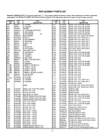
Page 94: ...16W 6 8K JB AP74 ONLY 0700055M CF 1 16W 12K JB R712 0700055M A CF 1 16W 12K JB 0700055M CF 1 16W 12K JB R713 0113727M CF SRD1 2P B 120 J 0700054M CF 1 16W lOK JB R714 0110101s MF IW 15 JS 0700063M CF 1116W 47K JB n R715 0700062M CF 1116W 39K JB AP73 ONLY 0700053M CF 1116W 8 2K JB A R715 0700063M CF 1 16W 47K JB AP74 ONLY 0700046M CF 1 16W 2 7K JB A R716 0700049M CF 1 16W 4 7K JB 0700046M CF 1 16W ...

Page 95: ...D 1 4P IOOK J WW 15W 0 62 KM CF SRD1 2P B CF SRDlRP B CF 8W 18 58 CF 1 16W 8 2K JB CF 1 16W 6 O JB CF 1 16W 1 5K JB CF l l 6W 2 7K JB CF l 1 6W 3 3K JB CF 1 16W 47 J CF 1 16W IOK JB CF l l 6W 1 2K JB CF 1 16W 680 JB MF O lOHMl 2W CF 1 8W 12K JB CF 1 8W IOK JB 1R920 0700047M 1CF 1 16W 3 3K JB 95 R922 R923 R925 R926 R929 R930 R931 R932 R933 R934 R935 R937 R940 R941 R942 R943 R944 R945 R946 R948 A R9...

Page 96: ...SASS B 6OSBX72B 7OSBX74B no7 FE00061 1 P TACT SWITCH AP73 ONLY 23 H512226 LOWER REAR BOARD 46UX5OBI51 K no9 FE00091 SWPOlNOl EVQQKH08Q 23 H512216 LOWER REAR BOARD 5OUX528 53K 23 H512228 LOWER REAR BOARD 6OUX54B 55K MISCELLANEOUS 23 H512225 LOWER REAR BOARD 50SBX70B 23 H512229 LOWER REAR BOARD 60SBX72B PH02574 CONTROL PANEL UX MODELS 70SBX74B 23 H512217 LOWER REAR BOARD 7OSBX74B PH04451 CONTROL PAN...

Page 97: ...JOO071 R SEMICONDUCTOR AGt5PC 152FS K2M 3D95 EY00791 PJX LEAD PLUGPIN A G832 CJ00071R SEMICONDUCTOR AGt5PC 152FS K2M D99 EY00791 PJX LEAD PLUGPIN A G861 CJOOO71 R SEMICONDUCTOR AGt5PC 152FS K2M 3DSt 2908947 12J CONNE L lOOO r G862 CJ0007tR SEMICONDUCTOR AGt5PC 152FS K2M IF91 2721351 FUSE HOLDER JSOI EROOt21 2L4P LEVER TERMINAL IFC 2998591 CONN W WIRE 4J W BOARD I AP74 ONLY JYOI ES001 12 PJFPJF 14P...

Page 98: ...BSlRZVUTWGX Al CP TAC L18X Al CP TAC L18P Al CP TAC L18X Al CP TAC L18P Al CP TAC LZOX Al ICP TAC LZOP Al CP TAC LZOX Al CP TAC LZOP Al lg yc y yG PIN CP TAC LIOP Al CP TAC LlOX Al CP TAC LlOP Al PLUG PIN SUB MINI 3P PIN POST PH 6P CONN 6P PH AP74 PLUG PIN SUB MINI 4 1 P PLUG PIN WITH BASE 1 P PLUG PIN WITH BASE 1 P PLUG PIN WITH BASE 3D Y C UNIT AP74 ONLY SP OSM 46UX5OBI51 K 8 5OUX52Bl53K SP OSM ...

Page 99: ...NOTES 99 ...

Reviews: