v
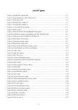
Figure 5-1 Software configuration of the J.NET module ................................................................................... 5-1
Figure 5-2 Flow of communication data of the communication control program .............................................. 5-2
Figure 5-3 S-register ........................................................................................................................................... 5-4
Figure 6-1 Example of calculating communication time when J.STATIONs are connected ............................. 6-2
Figure 8-1 Wiring required for external loopback check .................................................................................... 8-2
Figure 8-2 Switch settings of the J.NET module ................................................................................................ 8-4
Figure 8-3 TX and RX LEDs of the J.NET module ........................................................................................... 8-5
Figure 8-4 ERR LEDs of the J.NET module ...................................................................................................... 8-6
Summary of Contents for 510VE
Page 1: ...User s Manual Option J NET LQE540 E SEE 1 102 A ...
Page 2: ...User s Manual Option J NET LQE540 E ...
Page 27: ...This page is intentionally left blank ...
Page 35: ...This page is intentionally left blank ...
Page 73: ...This page is intentionally left blank ...


