8. Test and Maintenance Diagnosis
8-4
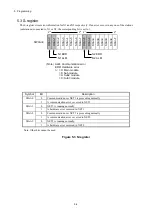
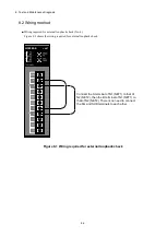
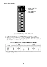
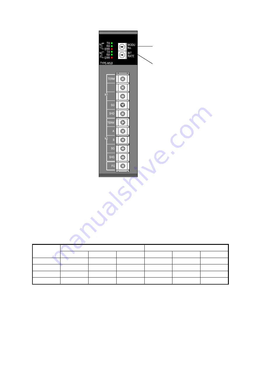
Figure 8-2 Switch settings of the J.NET module
(3) Set the CPU RUN/STOP switch and LADDER RUN/STOP switch of the CPU module to RUN.
(4) Turn on the power switch of the power supply module. This starts the Test and Maintenance operation.
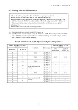
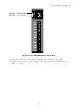
During the Test and Maintenance operation, the TX LED and RX LED are either on or blinking. Table 8-3
shows the LED states during the Test and Maintenance operation.
Table 8-3 LED states during the Test and Maintenance operation
Test item
N1 (NET1)
N2 (NET2)
TX LED
RX LED
ERR LED
TX LED
RX LED
ERR LED
T/M1
On
On
#
On
On
#
T/M2
Off
Blinking
#
Off
Blinking
#
T/M3
Off
On
#
Off
On
#
T/M4
On
On
#
On
On
#
#: The ERR LED (N1 and N2) turns on only when an error occurs.
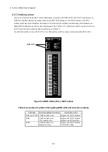
For details, see
8.4 Checking errors
.
MODU No. setting switch
Select a module.
BIT RATE setting switch
Select a test item.
LQE540-E
J.NET
A
B
Summary of Contents for 510VE
Page 1: ...User s Manual Option J NET LQE540 E SEE 1 102 A ...
Page 2: ...User s Manual Option J NET LQE540 E ...
Page 27: ...This page is intentionally left blank ...
Page 35: ...This page is intentionally left blank ...
Page 73: ...This page is intentionally left blank ...


