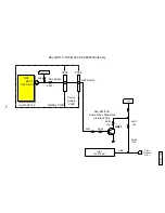
Pin 24 = FBP.
Combination of the following.
Fly back pulse
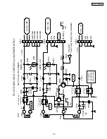
: 1.5V ~ 3.0V H-AFC: This input is received from the Horizontal Blanking (H. Blk)
signal generated in the Deflection circuit by Q706. This signal is used as a sample pulse in the
Horizontal AFC circuit, which synchronizes the Horizontal Drive signal with the incoming Video sync
signal input at pin 16. In Through Mode, pin 8.
Fly back puls e:
3.0V ~ 9.0V Max: This input is received from the Flex Converter and is a combination
of Horizontal and Vertical blanking signals.
H Blk from the Flex Converter Pin 12 through Q412
V Blk from the Flex Converter Pin 11 through Q411
Used within the Rainforest is for DC restoration, Pedestal level detection and Clamping signals, such as
Burst Gate Pulse.
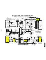
0.9 ~ 2.1V Half Tone
H-AFC 3.0V
SCP IN
3.7 ~ 9V
CLAMP
1.7 ~ 3.3V
Black Peak
FBP IN
YM/P-MUTE/
BLK
2.4 ~ 5.8V P Mute
Max 9V
BLK 1.5V
0 ~ 0.5V Internal
6.2 ~ 9V Blanking
Pin 17
Pin 24
Pin 52
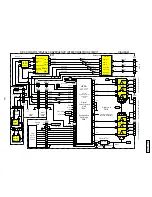
DP-2X RAINFOREST IC INFORMATION (I401)
Pin 17 = SCP.
Black Pe ak
: This input is utilized for establishing the Black Peak level used in Black Peak expansion
circuit. Here the Black Peak is expanded towards Black to increase the contrast ratio.
CLAMP
: The clamp pulse is utilized for DC restoration and blanking timing.
Pin 52 = YM/P- MUTE/BLK.
Combination of the following.
I NTERN AL
: 0.0V ~ 0.5V Used internal within the Rainforest IC.
HALFTONE:
0.9V ~ 2.1V: This input is received from the Microprocessor and is used to establish the
Transparency effect of OSD. This also mutes the video in exact timing with On Screen Display pulses
(OSD). Half Tone from the Microprocessor Pin 22 through Q415.
P MUTE
: 2.4V ~ 5.8V: Not Used.
DP27 DP27D
123
Summary of Contents for 51SWX20B
Page 55: ...55 DP27 27D SIGNAL BLOCK ASSEMBLY BACK TO ADJUSTMENTS ...
Page 56: ...56 DP27 27D DEFLECTION P W B BACK TO ADJUSTMENTS ...
Page 57: ...57 DP27 27D POWER SUPPLY P W B BACK TO ADJUSTMENTS ...
Page 58: ...58 DP27 27D CPT P W B BACK TO ADJUSTMENTS ...
Page 59: ...59 DP27 27D CONTROL P W B BACK TO ADJUSTMENTS ...
Page 60: ...60 DP27 27D TROUBLE SHOOTING FLOWCHART 1 NO RASTER AND NO POWER How to check LED s Diagnosis ...
Page 61: ...61 DP27 27D TROUBLE SHOOTING FLOWCHART ...
Page 62: ...62 DP27 27D TROUBLE SHOOTING FLOWCHART ...
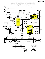
Page 83: ...83 DP27 27D DP2X Protection Circuit Block Diagram Deflection Power Supply ...
Page 84: ...84 DP27 27D DP1X Protection Circuit Block Diagram Signal Power Supply ...
Page 96: ......
Page 97: ......
Page 98: ......
Page 99: ......
Page 100: ......
Page 101: ......
Page 102: ......
Page 103: ......
Page 104: ......
Page 105: ......
Page 106: ......
Page 107: ......
Page 108: ......
Page 109: ......
Page 110: ......
Page 111: ......
Page 189: ...DP27 27D ...


