background image

[ NEW FEATURES ]

Lightweight and compact (5.3 kg)

Three-angle adjustable handle

Powerful 2,000 W (3-1/4 HP) motor (M 12VE)

The new M 12VE/12SE models are intended to significantly reduce the size, weight, and price relative to the
existing M 12V2/12SA2 models.
(1) Lightweight and compact (5.3 kg)
(2) Very competitive price
(3) Three-angle adjustable handle
(4) Powerful 2,000 W (3-1/4 HP) motor (M 12VE)

We aim to expand the sales of our routers with this new product.

LIST Nos.
M 12VE: 0674
M 12SE: 0673
Nov. 2009

PRODUCT NAME

Hitachi 12 mm (1/2”) Router

Models

  M 12VE

M 12SE

x

 Groove cutting, chamfering

x

 Window cutting, trimming

x

 Shaping and pattern cutting

MARKETING OBJECTIVE

APPLICATIONS

SELLING POINTS

SPECIFICATIONS AND PARTS ARE SUBJECT TO CHANGE FOR IMPROVEMENT.

Sales Division

M

Summary of Contents for 673

Page 1: ...3 kg 2 Very competitive price 3 Three angle adjustable handle 4 Powerful 2 000 W 3 1 4 HP motor M 12VE We aim to expand the sales of our routers with this new product LIST Nos M 12VE 0674 M 12SE 0673 Nov 2009 PRODUCT NAME Hitachi 12 mm 1 2 Router Models M 12VE M 12SE x Groove cutting chamfering x Window cutting trimming x Shaping and pattern cutting MARKETING OBJECTIVE APPLICATIONS SELLING POINTS ...

Page 2: ...nual_view_export Throughout this TECHNICAL DATA AND SERVICE MANUAL a symbol s is are used in the place of company name s and model name s of our competitor s The symbol s utilized here is are as follows Competitors Symbols Utilized Company Name Model Name C1 3612C C2 MAKITA 3612 D1 DW 625E D2 DEWALT DW 624 ...

Page 3: ...RISON WITH SIMILAR PRODUCTS 4 1 Comparison of Specifications 4 PRECAUTIONS ON SALES PROMOTION 5 1 Safety Instructions 5 2 Special Precautions 5 REPAIR GUIDE 6 1 Precautions on Disassembly and Reassembly 6 STANDARD REPAIR TIME UNIT SCHEDULES 12 Assembly Diagram for M 12VE Assembly Diagram for M 12SE ...

Page 4: ...11 7 lbs 5 3 kg 11 7 lbs 6 3 kg 13 9 lbs 6 2 kg 13 7 lbs 6 0 kg 13 2 lbs 5 8 kg 12 8 lbs 6 0 kg 13 2 lbs 6 0 kg 13 2 lbs Weight Catalog data 5 3 kg 11 7 lbs 5 3 kg 11 7 lbs 6 7 kg 14 8 lbs 6 6 kg 14 6 lbs 6 0 kg 13 2 lbs 5 8 kg 12 8 lbs 5 1 kg 11 2 lbs 5 1 kg 11 2 lbs Three angle adjustable handle The handle of this product is adjustable at three tilting angles The user can adjust the handle at an...

Page 5: ...at of the existing model and higher than that of the C1 in the practical working range of relatively light cutting work because it adopts a motor having the same rated power 2 000 W as that of the existing model while achieving a significant weight reduction Hitachi New Models Present Models Model M 12VE M 12SE M 12V2 M 12SA2 C1 C2 Armature s moment of inertia x 10 3 N m x 10 4 kg cm 3 0 3 0 4 6 4...

Page 6: ...Dustproof snap switch Weight 5 3 kg 11 7 lbs 5 3 kg 11 7 lbs Height min max 235 mm 9 1 4 300 mm 11 13 16 Standard accessories 2 Optional Accessories Dust collector set Straight guide Fine ajustment knob SPECIFICATIONS Voltage V Current A Input W 110 15 0 1 570 120 15 0 1 700 127 14 2 1 700 220 9 6 2 000 230 9 2 2 000 240 8 8 2 000 Parallel guide 1 Qty Collet chuck 12 mm or 1 2 1 Qty Template guide...

Page 7: ...No Yes No Yes No Yes No Stroke capacity mm 65 2 9 16 65 2 9 16 60 2 3 8 62 2 7 16 Quick fine cutting adjustment No Yes No Yes Angle adjustable handle Yes No No No Speed control dial position Top cover Handle Top cover Top cover Height Min to Max mm 235 to 300 9 1 4 to 11 13 16 255 to 320 10 to 12 19 32 237 to 297 9 21 64 to 11 11 16 231 to 295 9 to 11 39 64 Weight measured data kg 5 3 11 7 lbs 5 3...

Page 8: ... attached to the main body For the USA and Canada For Australia New Zealand Asia and South Africa 2 Special Precautions The Handling Instructions and caution plate describe precautions on using this router However salespersons should instruct customers to strictly observe the following precautions that require special attention 1 Groove cutting for a cutting depth of 20 mm or more with a straight ...

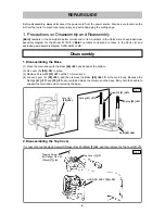
Page 9: ...embling the Base 1 Place the main body with the Base 68 64 positioned at the bottom 2 Fix Lever A 58 54 in place 3 Remove Screw M8 51 47 with a 13 mm wrench 4 Loosen Lever A 58 54 and then remove the Base 68 64 from the main body Because the Springs 41 37 and 55 51 are contained inside the columns on the base firmly hold the handle to support the main body when removing the base 2 Disassembling th...

Page 10: ...l M 12VE 6 Loosen the three Machine Screws W Washers M4 x 12 Black 64 60 and then remove the Bearing Cover 63 59 Pushing Button 66 62 and Lock Spring A 65 61 7 While being careful not to drop the core of the Armature 39 35 secure the Armature 39 35 with a vice 8 Use a wrench to turn the Thrust Nut 62 58 counterclockwise and remove it 9 Use a hand press to remove the Armature 39 35 from the End Bra...

Page 11: ...ch Holder 24 21 with the Switch 26 23 mounted from the Housing Ass y 36 32 loosen the screw fixing the switch terminal and then remove the lead wires 5 Loosen and remove the two Hex Hd Tapping Screws D5 x 70 35 31 6 Place the Housing Ass y 36 32 so that the end to be fitted to the End Bracket 45 41 faces down and then lightly tap the end face with a wooden or plastic hammer to remove the Stator As...

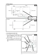
Page 12: ...s below 1 Internal Wiring 1 Be careful to prevent the lead wires from being caught between the housing assembly and top cover 2 Perform wiring carefully to prevent the lead wires from touching the conmitator of the armature x M 12VE Reassembly Switch Holder 21 Switch 23 Controller 9 Magnet pickup Dial Switch 26 Switch Holder 24 Fig 6 Fig 5 ...

Page 13: ... and Switch Holder 24 21 insert the lever of the switch correctly into the hole on the Lever 37 33 x M 12VE Red Switch White Black Stator Stator Armature Stator Dial Power source Control circuit ass y Switch Stator Armature Power source Noise Suppressor For UK Europe South Africa China Taiwan Fig 7 Fig 8 Fig 9 Lever of switch Switch 26 23 Lever 37 33 D12 internally toothed lock washer Switch Holde...

Page 14: ...䱏 䱏 䱏 䱏 䱏 䱏 䱏 䱏 䱏 䱏 䱏 䱏 䱏 䱏 䱏 䱏 䱏 䱏 䱏 䱏 䱏 䱏 䱏 䱏 䱏 3 4 r 0 7 N m 35 r 7 kgf cm Screw M8 51 47 䱏 䱏 䱏 䱏 䱏 䱏 䱏 䱏 䱏 䱏 䱏 䱏 䱏 䱏 䱏 䱏 䱏 䱏 䱏 䱏 䱏 䱏 䱏 䱏 䱏 䱏 䱏 䱏 䱏 䱏 䱏 䱏 䱏 䱏 䱏 䱏 䱏 9 8 r 2 0 N m 100 r 20 kgf cm Thrust Nut 62 58 䱏 䱏 䱏 䱏 䱏 䱏 䱏 䱏 䱏 䱏 䱏 䱏 䱏 䱏 䱏 䱏 䱏 䱏 䱏 䱏 䱏 䱏 䱏 䱏 䱏 䱏 䱏 䱏 䱏 䱏 䱏 䱏 䱏 䱏 䱏 䱏 17 2 r 2 5 N m 175 r 26 kgf cm 6 Checks after Reassembly After reassembly check the following 1 Confirm that the L...

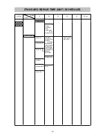
Page 15: ... Chuck Handle A B Set Sub Base Stopper Block Lever A Switch Controller Cord Cord Armor D10 1 Switch Holder Armature Rubber Ring Bearing Bushing Ball Bearing 6200VVCMPS2L Ball Bearing 6004VVCMPS2L Bearing Cover Magnet Mp Holder End Bracket Base Housing Ass y Stator Ass y STANDARD REPAIR TIME UNIT SCHEDULES ...

Page 16: ...45 501 506 503 505 504 508 7 8 1 9 4 20 19 16 11 10 12 13 14 22 23 25 26 24 5 6 27 30 29 28 31 32 34 35 38 39 36 37 40 41 55 43 44 46 56 57 58 59 43 42 46 60 61 62 63 64 65 67 68 69 70 51 53 52 50 47 48 49 54 17 40 15 3 33 502 507 2 21 66 42 18 509 ...

Page 17: ...ORD 1 CORD ARMOR D10 1 FOR TPE 9 331 810 CONTROLLER 100V 120V 1 9 331 811 CONTROLLER ASS Y 220V 240V 1 10 325 475 MAGNET 1 11 954 004 TAPPING SCREW D4 X 16 2 12 331 822 MP HOLDER 1 13 325 169 BEARING BUSHING 1 14 325 184 RUBBER RING 1 15 331 989 INTERNAL WIRE BLUE 1 15 331 979 INTERNAL WIRE WHITE 1 FOR USA CAN MEX PAN 120V 16 938 307 PILLAR TERMINAL 1 17 980 063 TERMINAL 1 18 937 631 CORD CLIP 1 1...

Page 18: ...45 331 817 END BRACKET 1 46 323 426 FELT 2 47 317 200 MACHINE SCREW W WASHERS M4 X 8 BLACK 1 48 962 569 WASHER B 1 49 971 858 SPRING A 1 50 302 196 MACHINE SCREW M5 X 20 BLACK 1 51 331 824 SCREW M8 1 52 302 197 MACHINE SCREW M5 X 35 BLACK 1 53 302 012 NUT M5 BLACK 2 54 331 826 STOPPER BLOCK 1 55 303 317 SPRING 1 56 971 848 LOCK PIECE 1 57 325 187 LOCK SCREW M10 1 58 323 923 LEVER A 1 59 997 314 MA...

Page 19: ...12MM 1 FOR GBR USA CAN 509 331 815 CASE 1 FOR USA CAN DESCRIPTION REMARKS 601 307 801 COLLET CHUCK 1 2 1 EXCEPT FOR GBR USA CAN BRA PAN MEX AUS NZL VIE SAF MAL THA 602 323 293 COLLET CHUCK 1 4 1 EXCEPT FOR GBR USA CAN BRA PAN MEX AUS NZL VIE SAF MAL THA 603 997 466 DUST COLLECTION ADAPTER SET 1 604 956 794 TRIMMER GUIDE 1 605 331 815 CASE 1 EXCEPT FOR USA CAN 4 Printed in Japan 10 09 091021N ALTER...

Page 20: ...9㨯10㨯21 41 501 506 503 505 504 508 4 5 1 8 17 16 13 9 10 11 19 20 22 23 21 2 3 24 27 26 25 28 30 31 34 35 32 33 36 37 51 39 40 42 52 53 54 55 39 38 42 56 57 58 59 60 61 63 64 65 66 47 49 48 46 43 44 45 50 14 36 12 7 29 502 507 6 18 38 15 62 ...

Page 21: ... 9 954 017 TAPPING SCREW D4 X 12 2 10 325 226 BEARING BUSHING 1 11 325 184 RUBBER RING 1 12 331 989 INTERNAL WIRE BLUE 1 12 331 979 INTERNAL WIRE WHITE 1 FOR MEX PAN 120V 13 938 307 PILLAR TERMINAL 1 14 980 063 TERMINAL 1 15 937 631 CORD CLIP 1 16 984 750 TAPPING SCREW W FLANGE D4 X 16 2 17 953 327 CORD ARMOR D8 8 1 17 938 051 CORD ARMOR D10 1 1 18 NAME PLATE 1 19 620 0VV BALL BEARING 6200VVCMPS2L...

Page 22: ...1 44 962 569 WASHER B 1 45 971 858 SPRING A 1 46 302 196 MACHINE SCREW M5 X 20 BLACK 1 47 331 824 SCREW M8 1 48 302 197 MACHINE SCREW M5 X 35 BLACK 1 49 302 012 NUT M5 BLACK 2 50 331 826 STOPPER BLOCK 1 51 303 317 SPRING 1 52 971 848 LOCK PIECE 1 53 325 187 LOCK SCREW M10 1 54 323 923 LEVER A 1 55 997 314 MACHINE SCREW W WASHERS M6 X 10 1 56 307 100 TAPPING SCREW D5 X 50 4 57 600 4VV BALL BEARING ...

Page 23: ...PCS 2 508 325 199 COLLET CHUCK 12MM 1 FOR GBR MEX DESCRIPTION REMARKS 601 307 801 COLLET CHUCK 1 2 1 EXCEPT FOR GBR BRA PAN MEX AUS NZL VIE SAF MAL THA 602 323 293 COLLET CHUCK 1 4 1 EXCEPT FOR GBR BRA PAN MEX AUS NZL VIE SAF MAL THA 603 997 466 DUST COLLECTION ADAPTER SET 1 604 956 794 TRIMMER GUIDE 1 605 331 815 CASE 1 4 Printed in Japan 10 09 091021N ALTERNATIVE PARTS OPTIONAL ACCESSORIES STAND...

Reviews: