background image

10

 -

English

C) Start the engine. (Refer to the Engine Manual

accompanying this unit.)

D) When the engine has run for 1-2 minutes, flip toggle

back to the original position.

The operation of this compressor is automatic and is
controlled by the pilot valve which idles it when the pressure
in the air-tank reaches the maximum level and restart it
when the air pressure drops during use to the restart level.
The pilot valve is preset by the manufacturer and must not
be modified in any way.

WARNING:

If you notice any unusual noise or vibration, stop
this compressor.

2.

Adjustment of working pressure
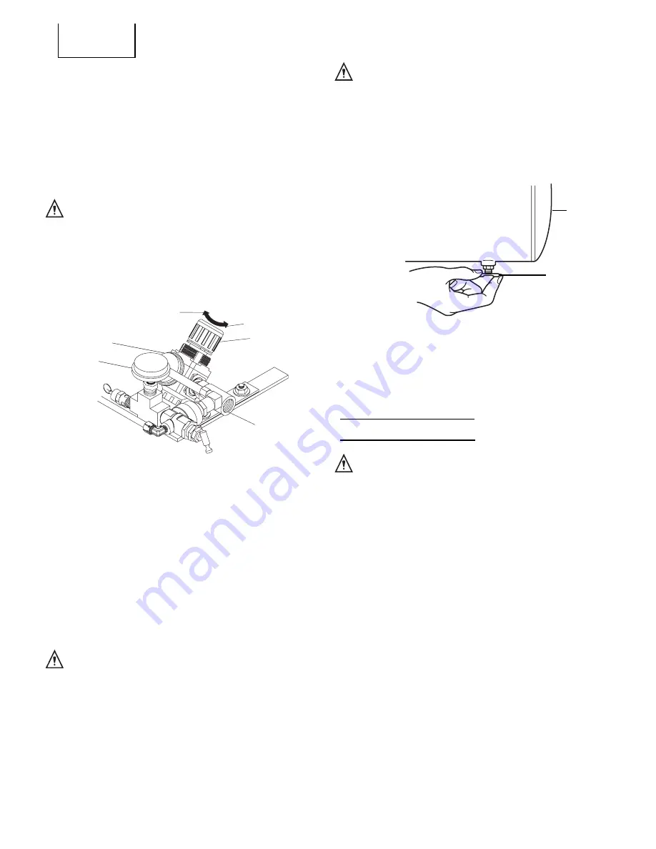
The air pressure coming from the air tank is controlled by
the regulator knob (Fig. 5). Turn the pressure regulation
knob clockwise to increase discharge pressure, and
counterclockwise to decrease discharge pressure.

The outlet pressure gauge indicates the air pressure
available at the outlet side of the regulator. This pressure
is controlled by the regulator and is always less or equal
to the air tank pressure.
The air tank pressure gauge indicates the reserve air
pressure in the air tank(s).
When adjusting the pressure, check and make sure that
a pressure gauge  for the tank has the pressure level that
is higher than that of the pressure to be adjusted.
It is also imperative that you make adjustment by slowly
starting up the pressure from the level that is lower than the
pressure to be adjusted.

WARNING:

Check the manufacturer’s maximum pressure
rating for nailers, staplers and accessories.
Compressor outlet pressure must be regulated
so as to never exceed the maximum pressure
rating of the nailers, staplers and accessories.

3.

Shutdown
A)

To stop this compressor, move the engine switch to
the “Off” position. (Refer to the Engine Manual
accompanying this unit.)

B)

Gradually open the drain cock, take out the drainage
and all the compressed air inside the tank to prevent
any internal corrosion of the tank. (Fig. 6)

WARNING:

When the tank gets corroded, there is a
risk of breakdown. Accordingly, be sure
to discharge the drain inside the tank
after each use.
The drain contains moisture in the air,
abrasion particles, rust, etc. To
discharge the drain, therefore, gradually
open the drain cock, and be careful not
to point it at your face or eye.

C) Allow this compressor to cool down.
D) Wipe this compressor clean and store in a safe, non-

freezing area.

WARNING:

Always stop the engine and pull out the
spark plug cap  to prevent any sudden start
of the engine and remove this compressed
air from the air tank before performing the
maintenance operations.

Read the instruction manual before performing
maintenance. The following procedures must be
performed when stopping this compressor for
maintenance or service.

A)

Turn off this compressor.

B)

Disconnect spark plug wire from engine.

C) Open all drains.
D) Wait  for this compressor to cool down before starting

service.

MAINTENANCE

Fig. 5

Fig. 6

Tank

Drain cock

Increase: Clockwise

Decrease:
Counter clockwise

Knob of
pressure
regulator

Joint of regulator
mounting bracket

Outlet pressure gauge

Tank
pressure gauge

Summary of Contents for AC1-PH55-08H

Page 1: ...odily injury Compressor manual this manual and engine manual contains important information about product safety Please read carefully and fully understand the compressor manual this manual and engine manual before operating the compressor Please keep the compressor manual this manual and engine manual available for others before they use the compressor 37 0743 110602 Copyright 2002 ...

Page 2: ...SAFETY IMPORTANTSAFETYINSTRUCTIONS FOR USE OF THE COMPRESSOR 4 REPLACEMENTPARTS 6 Page OPERATIONANDMAINTENANCE NAMEOFPARTS 7 SPECIFICATIONS 8 APPLICATIONS 8 PRIOR TO OPERATION 8 OPERATION 9 MAINTENANCE 10 SERVICE AND REPAIRS 11 PARTSLIST 12 CONTENTS English ...

Page 3: ...the SAFETY sectionofthisInstructionManualandinthesectionswhichcontain the operation and maintenance instructions HazardsthatmustbeavoidedtopreventbodilyinjuryormachinedamageareidentifiedbyWARNINGSonthecompressor and in this Instruction Manual Never use this compressor in a manner that has not been specifically recommended by HITACHI MEANINGS OF SIGNAL WORDS WARNING indicates a potentially hazardou...

Page 4: ...KEEPWORKAREACLEAN Cluttered areas invite injuries Always clear all work areas of unnecessary tools debris furniture etc 8 CONSIDERWORKAREAENVIRONMENT Don t expose this compressor to rain Don t use this compressor in damp or wet locations Keep work area well lit and well ventilated Operate this compressor at a stable place all the time Do not operate in flammable environment This compressor produce...

Page 5: ...pressor Do not operate at pressure or speed in excess of manufacturer s recommendations Always contact the Hitachi authorized service center for any repairs Unauthorized modification may impair this compressor s performance and result in accident or bodly injury 20 TURN OFF THE ENGINE SWITCH WHEN THIS COMPRESSOR IS NOT USED When this compressor is not used push the knob of the engine switch OFF an...

Page 6: ...n of tank or explosion of those damaged component parts Furthermore gasoline which spilled out by those damages may have a great risk of a fire When there is any deformation and damage on the handle it may drop during transport resulting in a accident of injury Before carrying this compressor switch off the engine and discharge the drain inside the air tank Be cautious enough to make sure that the...

Page 7: ...ion Manual and Engine Instruction Manual are designed to assist you in the safe operation and maintenance of this compressor Some illustrations in the Compressor Instruction Manual this Instruction Manual and Engine Instruction Manual may show details or attachments that differ from those on your own compressor Fig 1 ...

Page 8: ... in an area where there is evidence of oil or gas leaks where flammable gas vapors or materials may be present where air temperatures fall below 14 F or exceed 104 F where extremely dirty air or water could be drawn into this compressor 3 Gasoline engine A Review page 5 25 before fueling WARNING Donotallowtheengineormufflertocome in contact with flammable vapors combustible dust gases or other com...

Page 9: ...ibilityof spilled fuel which may cause a fire Do not operate this compressor if gasoline is spilled Wipe thiscompressorcleanandmove it away from the spill Avoid creating any ignitionuntil the gasolinehas evaporated Allowapproximately1 4 oftankspaceforfuel expansion WARNING Always store fuel away from this compressor while it is running or hot H Refer to the engine manual for all necessary maintena...

Page 10: ...he manufacturer s maximum pressure rating for nailers staplers and accessories Compressoroutletpressuremustberegulated so as to never exceed the maximum pressure rating of the nailers staplers and accessories 3 Shutdown A To stop this compressor move the engine switch to the Off position Refer to the Engine Manual accompanying this unit B Gradually open the drain cock take out the drainage and all...

Page 11: ...pen the drain valve and drain out the air in the tank Fig 6 Close tightly when drained 3 Maintenance chart The pump oil must be changed after the first 50 hours of operation and every 200 hours or 3 months whichever comes first Open the pump oil cock and replace pump oil Fig 1 As reguards the engine follow instructions in the engine manual Every 2 years an Authorized Service Technician should chec...

Page 12: ... 12 EC 25E ...

Page 13: ...p 724019 42 0011 2 61 Decal Warning Beltguard in Place See 34 9016 CF N A Sep 1 20 Hose One Foot Required 724020 15 0007 1 62 Beltguard Back See 724063 33 0020 N A Sep N A Sep 1 21 Locknut 724024 30 0157 10 63 Bolt 724066 27 0074 2 22 Washer 724022 28 0003 14 64 Decal Check Oil Tape See 34 9016 CF N A Sep 2 23 Regulator Mounting Bracket 724023 20 0421A01 1 65 Key 724068 43 0073 1 24 Bolt 724021 27...

Page 14: ... 14 EC 25E ...

Page 15: ...31 Snap Ring See 724142 70 0329 N A Sep N A Sep 4 11 Valve Stop See 724140 70 0327 N A Sep N A Sep 2 32 Wrist Pin See 724142 70 0329 N A Sep N A Sep 2 12 Outlet Reed Valve See 724140 70 0327 N A Sep N A Sep 2 33 Piston See 724142 70 0329 N A Sep N A Sep 2 13 Valve Plate N A N A 1 34 Bottom Rail See 724141 70 0328 N A Sep N A Sep 2 14 Inlet Reed Valve See 724140 70 0327 N A Sep N A Sep 2 35 Expande...

Page 16: ...ercity Tower A 15 1 Konan 2 chome Minato Ku Tokyo 108 6020 Japan Distributed by Hitachi Koki U S A Ltd 3950 Steve Reynolds Blvd Norcross GA 30093 Hitachi Koki Canada Co 6395 Kestrel Road Mississauga ON L5T 1Z5 108 Code No C99109061 Printed in U S A ...

Reviews: