background image

INSTALLATION  
& MAINTENANCE 
MANUAL


airCloud Gateway

AIR CONDITIONER 
MANAGEMENT SYSTEM

MODEL

HC-IOTGW

A10013740A

Summary of Contents for airCloud HC-IOTGW

Page 1: ... INSTALLATION MAINTENANCE MANUAL airCloud Gateway AIR CONDITIONER MANAGEMENT SYSTEM MODEL HC IOTGW A10013740A ...

Page 2: ...Login 20 5 2 Device List 20 5 3 Rediscover Devices 21 5 4 Ethernet Information 21 5 5 Certificate 23 5 6 Time Zone Time Setting 23 5 7 Account Management 24 5 8 Software Update 24 5 9 Indoor Unit Status 25 5 10 Indoor Control 25 5 11 RC Operation Prohibit 26 5 12 Outdoor Unit Status 26 5 13 Temperature Unit Selection 26 6 Reset to Factory Default 27 7 Indication Normal and Abnormal 27 8 Maintenanc...

Page 3: ...r dealer This manual provides common descriptions basic and advanced information to maintain and service this airCloud Gateway which you operate as well for other models This manual should be considered as a permanent part of the airCloud Gateway equipment and should remain with the airCloud Gateway equipment Product Inspection upon Arrival 1 Upon receiving this product inspect it for any damages ...

Page 4: ...y equipment When transporting be careful when picking up moving and mounting these units Although the unit may be packed using plastic straps do not use them for transporting the unit from one location to another Do not stand on or put any material on the unit Get a partner to help and bend with your knees when lifting to reduce strain on your back Sharp edges or thin aluminum fins on the air cond...

Page 5: ...seating areas in restaurants and so forth For these locations or social venues use specialized units with oil resistant features built into them In addition use a specialized ceiling fan designed for restaurant use These specialized oil resistant units can be ordered for such applications However in places where large quantities of oil can splash onto the unit such as a factory even the specialize...

Page 6: ... electrical noise to reduce the potential for communication errors When shielded cabling is applied proper bonding and termination of the cable shield is required Plenum and riser ratings for communication cables must be considered per application and local code requirements Be sure to install circuit breakers ground fault interrupter isolating switch molded case circuit breaker and so on with the...

Page 7: ... Remote Access App Web Local Access Web Browser airCloud Pro 4G Module optional Power Line Power Line H LINK Ethernet HUB 4G Figure 2 1 Sample of System Configuration 1 Hitachi Johnson Controls Air Conditioning provides the airCloud Gateway 4G Module optional and Cloud Platform others are prepared by user 2 Please refer to 4 App Operation to get more information for remote access 3 Up to 16 outdoo...

Page 8: ...h Product Symbol Instruction Figure 2 2 Parts Names 2 3 Key Components The following figure shows the airCloud Gateway without the cover Each name and function are as follows Regarding how to connect each terminal refer to 3 2 1 Wiring Procedures Regarding how to set each switch refer to 3 2 3 Switch Setting Procedures SD Card Slot Insert SD card DC5V Socket Power DC5V supply for mainboard DIP Swi...

Page 9: ...tion Method Asynchronous Communication Speed 9600 bps Wire Length of Connecting Cable Less than 1 000m 3 281 ft Units Connected Qty Up to 16 outdoor units and 80 indoor units 32 outdoor units and 64 indoor units excluding H LINK ǁ up to 16 outdoor units and 64 indoor units For Combined Use PSC A64GT PSC A32MN NOTE 1 RC less indoor units can not be connected to the system where 2 or more central co...

Page 10: ... to 3 2 Electrical Wiring for wiring and switch settings Check the POWER LED lights On and ERROR LED OFF Refer to 7 Indication Normal and Abnormal for indication details of LEDs Refer to 3 3 Test Run for turning ON to perform test run Installation Tool List No Name Picture Remarks 1 Drill Diameter 6mm 2 Wire striper 3 Crimping plier 4 Screwdriver Cross screwdriver Diameter 6mm Length less than 240...

Page 11: ...4G module is selected to connect with cloud place where 4G signal can be covered and not inside metal box 3 1 2 Packing List Check for the following components before installation Table 3 1 Components List Description Appearance Quantity Remarks mm airCloud Gateway 1 Expansion Pipe 4 Φ6 30 Self tapping Screw for Expansion Tube 4 M3 5 35 Line Pressing Board 1 Self tapping Screw for Line Pressing Bo...

Page 12: ... 1 Installation Location 2 There are two mount methods Wall mount and DIN rail mount For any installation method ensure that the wire outlet faces the floor and keep the airCloud Gateway mounted vertical not horizontal See the example below Wire outlet faces the floor CORRECT INCORRECT Figure 3 2 Direction for Installing ...

Page 13: ... such as cement marble structure etc b 1 Drill holes in the wall please refer to the figure below for the hole position and size insert the wall plugs into the holes b 2 Remove the cover of the airCloud Gateway Firmly fix the gateway on wall through foot hole with self tapping screws Drill a hole with 40mm depth and 6mm diameter on the wall Insert the expansion pipe into the hole Place the body in...

Page 14: ... 3mm 185 5 0 3mm Four screw mounting holes Figure 3 5 Install on Non wood Wall 2 2 DIN rail installation a Firmly fix the rail on the wall DIN guide rail DIN guide rail self prepared Figure 3 6 DIN Rail Installation ...

Page 15: ... the DIN Rail 3 2 Electrical Wiring Read and understand 1 Safety Summary in this manual well before performing wiring work Wiring work for power line communication with air conditioners H LINK and Ethernet cable LAN with cloud are required Note that wiring work for communication with external devices is also required for any external device connected to the system Ensure that the power line is tur...

Page 16: ... Press two snap joints at the lower end of the upper cover remove the cover Screw Open the top cover in the direction of the arrow Remove the screw in the direction of the arrow Figure 3 8 Remove the Upper Cover 4 Remove the screws on the power board cover with a screwdriver then remove the power board cover Remove screw Remove screw Figure 3 9 Remove the Cover of Power Board ...

Page 17: ... terminal to fix wire 4 Fix each round terminal to terminals with screw 5 Fix cable with line pressing board Type of Wiring H LINK Communication Line LAN Cable Specification 5VDC IEEE802 3 Compliant 100BASE TX 10BASE T Wiring Length Less than 1 000m 3 281ft Less than 100m 328 1ft Cable Specification AWG21 0 75mm2 to AWG16 1 25mm2 LAN Cable CAT 5 or more Terminals Connector M2 5 Screw Terminal RJ45...

Page 18: ... 10 Fix the Cover of Power Board 3 2 2 4G Module Installation 4G Module is optional for airCloud Gateway If use 4G module insert the 4G module on USB port as below 4G Module Figure 3 11 Insert 4G Module NOTE If having 4G and LAN simultaneously 4G is perference when connecting to cloud ...

Page 19: ...second protection fuse for H LINK is inactive OFF When the first protection fuse for H LINK is blown set 2 pin on DS3 to ON to make short circuit between fuse terminals 2 ON H LINK Terminal Resistance is active OFF H LINK Terminal Resistance is inactive OFF Ensure that no other terminal resistance exists on the same H LINK when activating terminal resistance from the airCloud Gateway NOTE DHCP mod...

Page 20: ... Step 1 Connect your PC and airCloud Gateway directly with Ethernet cable as below LAN Wiring Terminal Ethernet Cable Figure 3 13 Connect PC to airCloud Gateway Step 2 Make sure your PC are in the same Sub network with airCloud Gateway follow the procedures below 1 Go to Start Control Panel Network and Sharing Center Local Area Connection Properties Internet protocol version 4 TCP IP4 to set the I...

Page 21: ... please remove the other central controllers before powering on airCloud Gateway 3 3 1 AC System Connection Check The connection check starts after startup completed While airCloud Gateway is checking connection the ERROR LED flashes every 5 seconds Connection check completes in approximately several minutes Upon completion the ERROR LED goes off 3 3 2 Cloud Connection Check The cloud connection c...

Page 22: ...gh local Web Please go head 5 1 Login Open the web browser in PC enter the airCloud Gateway s IP address in address bar input the user name and password in the login screen Please get the default user name and password from the Appendix Ⅰ of this manual Figure 5 1 Login 5 2 Device List The initial screen is as below Figure 5 2 Device List Login airCloud Gateway from web browser check the system co...

Page 23: ...iscover Devices Otherwise the changing will not express until you perform this action NOTE This operation will lead the airCloud Gateway restart please wait the airCloud Gateway restart completing firstly and then refresh the web browser and re login to check the changes of Device List 5 4 Ethernet Information In DHCP mode only ethernet information can be checked In Static mode LAN static configur...

Page 24: ...P Address and related parameters Figure 5 4 LAN Static Configuration 2 Click Save to save the setting 3 Click OK in the displayed confirmation screen This will restart the airCloud Gateway Figure 5 5 Confirmation Screen Proxy Information Settings 1 Tick Proxy Enable 2 Set proxy information For proxy configuration problems please contact local IT personnel Figure 5 6 Proxy Information Settings ...

Page 25: ...rity please contact network administrator DHCP mode and static mode are applicable after proxy configuration 5 5 Certificate User can import the root Certificate into the trusted certificates of airCloud Gateway 1 Click Certificate File under Menu 2 Click Select File and choose the certificate file in PC 3 Click Upload Figure 5 7 Certificate Upload 5 6 Time Zone Time Setting Please set the correct...

Page 26: ...edures below 1 Select Software Updates from Setting menu Figure 5 10 Software Update 2 Select the software package file name W XXXX YYYY zip please confirm the package file is provided from official channel from your PC clicking the Upload button Please contact your local contractor if you have any problems For software package access please contact via the service mailbox E mail JCH IoT Service j...

Page 27: ...information Figure 5 12 Indoor Unit Status 5 10 Indoor Control The Control area is below the Status area From the control area change the operation mode as below Figure 5 13 Indoor Control Press Set to send command to indoor confirm the indoor status changed from the status area ...

Page 28: ... cannot be used In this case none of the central controller shall set RC operation prohibit function Setting RC operation prohibit in such scenario may cause malfunction On wall type if RC is connected RC operation prohibit function will be available 5 12 Outdoor Unit Status Click outdoor name item in the device list page check the status of outdoor unit Figure 5 15 Outdoor Unit Status 5 13 Temper...

Page 29: ...s manual Web Server Password After restoring factory settings user needs to set the DS1 Pin1 Pin4 to the normal startup mode and power on again Restoring factory settings will clear previously added certificates Since the connection information is also removed when resetting to factory default it will check connection again at next power on 7 Indication Normal and Abnormal The indication of LEDs a...

Page 30: ...n checking completed Flashes once in 5 sec Repeated N A 7 Communication failure with air conditioners After turning on the power on normal mode completed connection checking with air conditioners and detected communication failure with 1 or more air conditioners Communication on all the detected air conditioners is successfully established Flashes once in 3 sec Repeated 60 61 64 65 8 Combined with...

Page 31: ...ered ON Power ON all equipment Does H LINK wiring meet specification requirement Use 0 75 1 25mm2 standard and shielded cable with a length of 1 000m 3 281ft or shorter Doesn t ERROR LED flashes once 5 seconds repeated airCloud Gateway is checking connection Please wait If the situation keeps more than sixty minutes please checking wiring and address setting on air conditioners and perform connect...

Page 32: ...gher with length of 100m 328ft or shorter Is LAN cable and HUB free from loose connections shorted wires or other issues Replace with new ones Does the LAN LED stay OFF If none of the above applies to the circumstances and phenomenon described on the left remains airCloud Gateway may have an internal defect Contact your dealer or distributor 8 2 Regular Inspection In order to maintain the normal o...

Page 33: ...22 Japan E mail JCH IoT Service jci hitachi com 2019 Hitachi Johnson Controls Air Conditioning Inc Specifications in this catalogue are subject to change without notice in order that Hitachi Johnson Controls may bring the latest innovations to customers 2020 04 Ver F Printed in China ...

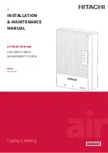
Page 34: ... airCloud Gateway 空調機管理系統 安裝 維護手冊 型號 HC IOTGW ...

Page 35: ...3 2 配線連接 40 3 3 試運轉 45 4 App 操作 45 5 用於固件更新的本地網絡 46 5 1 登錄 46 5 2 設備清單 46 5 3 重新搜索設備 47 5 4 網絡資訊 47 5 5 證書 49 5 6 時區 時間設定 50 5 7 帳戶管理 50 5 8 軟體更新 51 5 9 室內機狀態 51 5 10 室內機控制 52 5 11 線控器禁止 52 5 12 室外機狀態 53 5 13 溫度單位選擇 53 6 恢復出廠設置 53 7 LED 顯示 正常與異常 54 8 維護和服務 55 8 1 異常時的處理方法 55 8 2 定期檢查 56 9 記憶卡 56 ...

Page 36: ...31 CN 1 安全須知 airCloud 閘道器 airCloud 閘道器 HC IOTGW HO2019261F 3m 帶有聚氯乙烯 PVC 四氟乙烯 TFE 聚四氟乙烯 PTFE 氟化乙丙烯 FEP 和氯丁橡膠或聚醯亞胺 絕緣的導線和電纜 本手冊為 airCloud 閘道器專用 請配合所組合之空調機附屬的手冊一起使用 本手冊請務必移交給下一階段之工事施工者 最後交由顧客保管 安裝維護說明書 ...

Page 37: ...個空調機和連接 到系統的設備的安裝和維護手冊 遠端訪問 App Web 本地訪問 Web Browser 電源線 H LINK 4G 電源線 airCloud Pro 4G模組 可選 乙太網 HUB 雲端平台 圖 2 1 系統配置示例 1 日立江森空調機公司提供 airCloud 閘道器和 4G 模組 選配 其它由用戶自備 2 若需獲取更多遠端訪問資訊 請參閱 4 App 操作 3 最大可連接室外機 16 台 室內機 80 台 或連接室外機 32 台 室內機 64 台 非 H LINK Ⅱ 最大可達外機 16 台 室內機 64 台 ...

Page 38: ...K通訊 H LINK LED燈閃爍 4G LINK 4G信號強度顯示 圖 2 2 各部品名稱 2 3 關鍵部品 圖 2 3 表示已卸下頂蓋的設備 名稱和功能如下 電源端子的接續方法參照 3 2 1 接線程式 各 開關的設置參照 3 2 3 開關設置方法 SD卡槽 SD卡安裝位置 DC5V插座 DC5V 主機板 電源連接端 指撥開關DS1 模式設置 電源 AC100 240V 保險絲 電源 AC100 240V 電源連接端 USB埠 4G模組接入埠 H Link保險絲 H Link第一個保險絲 H Link保險絲 H Link第二個保險絲 DIP 開關 DS3 H Link終端電阻和保險絲開關設定 H Link 端子台 H Link配線使用 RS485 端子台 RS485 配線使用 圖 2 3 內部元件名稱 ...

Page 39: ...性 2 線式 通訊方式 半雙工 同步方式 非同步 通訊速率 9600 bps 配線長度 1000m 3281ft 以下 空調機連接台數 Qty 最大可連接室外機 16 台 室內機 80 台 或連接室外機 32 台 室內機 64 台 非 H LINK Ⅱ 最大可達外機 16 台 室內機 64 台 並聯使用 PSC A64GT PSC A32MN 注 1 同一 H LINK 下 併用兩台以上集中控制器的場合 室內機必須接續遙控器 注 2 一個 H LINK 系統只能有 1 個 airCloud 閘道器 一個 H LINK 系統最多可包含 8 個集中 控制器 注 3 併用時 不能使用遙控器操作禁止機能 表 2 3 LAN 乙太網 通訊規格 項目 規格 通訊物件 乙太網 HUB 通訊線 LAN 乙太網 通訊方式 IEEE 802 3 標準 10BASE T 100BASE TX 配線總長 100m...

Page 40: ...電運轉 1 安裝指導 2 接線 3 試運轉 4 LED顯示檢查 請仔細閱讀 3 1 安裝事項 並進行安裝工作 請仔細閱讀 3 2 配線連接 並進行接線連接 確認電源LED指示燈開啟和錯誤警報LED關閉 參照 7 LED顯示 正常與異常 確認LED運轉狀態 請仔細閱讀 3 3 試運轉 接通電源並試運轉 安裝工具清單 No 名稱 圖片 備註 1 電錘 半徑 6mm 2 電線劃線器 3 壓線鉗 4 螺絲刀 十字螺絲刀 半徑 6mm 長度 少於 240mm 5 尺子 ...

Page 41: ...全須知 2 可使用螺絲將 airCloud 閘道器牢固地固定在牆壁或 DIN 導軌上 3 不能隨意進出的場所 例如 在控制台內 4 如選擇 4G 模組與雲端連接 則該場所需涵蓋 4G 訊號 3 1 2 裝箱單 安裝前檢查以下元件 表 3 1 元件清單 描述 外觀 數量 備註 mm airCloud 閘道器 1 膨脹管 4 Φ6 30 自攻螺絲 膨脹管用 4 M3 5 35 壓線板 1 自攻螺絲 壓線板用 2 M4 14 安裝 維護手冊 1 安裝 維護手冊 歐洲版 1 接線端子 2 RVN 1 25 3 ...

Page 42: ...37 CN 3 1 3 安裝程式 1 確保安裝空間 如圖 3 1 所示 20mm 20mm 20mm 250mm 100mm 圖 3 1 安裝位置 2 安裝有以下兩種類型 牆壁安裝和 DIN 導軌安裝 對於任何安裝方法 請確保電線出口朝向地面並使 airCloud 閘道器垂直安裝而非水平安裝 見以下示例 配線出口朝向地面 正確 錯誤 圖 3 2 安裝方向 ...

Page 43: ...airCloud 閘道器固定在牆上 沿箭頭方向 卸下螺絲 沿箭頭方向 打開上蓋 四個螺絲 安裝孔 圖 3 3 木牆上安裝方法示意圖 b 非木板牆 如水泥 大理石結構等 b 1 在牆上鑽孔 孔位置和尺寸請參考下圖 將牆上插頭插入孔中 b 2 取下 airCloud 閘道器的蓋子 使用自攻螺絲通過腳孔牢固地將 airCloud 閘道器 固定在牆上 在牆體上鑽40深度 的直徑為6毫米的孔 6 將膨脹管塞 進牆體孔內 將本體放置帶 牆體對應位置 用自攻螺絲將本機裝到 牆上 扭矩為1 0 N m 圖 3 4 安裝在非木板牆上 ...

Page 44: ...9 CN 130 5 0 3 mm 185 5 0 3 mm 四個螺絲 安裝孔 圖 3 5 非木牆上安裝方法示意圖 2 2 DIN 導軌安裝 a 將 DIN 導軌固定在牆上 DIN導軌 圖 3 6 DIN 導軌安裝 注 自備 b 使用插銷將 airCloud 閘道器安裝到導軌上 將本體下部中間插銷往 下拉 同時嵌入導軌 將插銷向上推 牆壁 導軌 插銷 牆壁 導軌 110mm 插銷 圖 3 7 安裝至導軌 ...

Page 45: ...空調機 H LINK 連接通信 的線和與雲端連接的乙太網絡線 LAN 等接線工作 請注意 連接到系統的任何外部設備也需要 與外部設備進行通信的接線工作 在執行任何接線工作前 請確保電源線已關閉 3 2 1 接線程式 1 進行任何接線工作前 確保電源線和連接設備的電源都已關閉 2 擰下底部螺絲 3 按住上蓋下端的兩個卡扣 取下蓋子 螺絲 沿箭頭方向 打開上蓋 沿箭頭方向 卸下螺絲 圖 3 8 取下上蓋 4 用螺絲起子卸下電源板蓋上的螺絲 拆下電源板蓋 卸螺絲 卸螺絲 圖 3 9 拆下電源板蓋 ...

Page 46: ...N m 螺絲鎖付扭矩 0 25 N m 1 將電線從電源線出口中取出 2 將電線插入圓形端子 3 壓接圓形端子以固定電線 4 用螺絲將每個圓形端子固定到端子上 5 用壓線板固定電纜 接線類型 H LINK 通信線路 LAN 電纜 規格 5VDC 符合 IEEE802 3 標準 100BASE TX 10BASE T 接線長度 1000m 3281ft 以下 100m 328ft 以下 電纜規格 AWG21 0 75mm 2 至 AWG16 1 25mm 2 LAN 電纜 CAT5 或更高 端子 連接器 M2 5 螺絲端子 RJ45 連接器 連接程式 無極 螺絲鎖付扭矩 0 4N m 壓接圓形端子以連接電線 電線從 H LINK 線路中接出 用螺絲將每個圓形端子固定到端子上 將電線從 LAN 線路中接出 插入連接器 直到聽到鎖定聲音 注 電源線與通訊線之間距離大於 150mm ...

Page 47: ...42 CN 6 用螺絲固定電源板蓋 螺絲鎖付扭矩 0 6 N m 圖 3 10 固定電源板蓋 3 2 2 4G 模組安裝 4G 模組是 airCloud 閘道器的選配部分 如果使用 4G 模組 請在 USB 埠上插入 4G 模組 如下所示 4G 模組 圖 3 11 插入 4G 模組 注 LAN 和 4G 同時連接 雲端連接時首選 4G ...

Page 48: ... 2 OFF ON OFF OFF 3 ON ON OFF ON 4 OFF OFF ON OFF DS3 2 位 DSW 1 ON H LINK 的第 2 個保護保險絲有效 OFF H LINK 的第 2 個保護保險絲無效 OFF 當 H LINK 的第 1 個保護熔絲熔斷時 將 DS3 的 Pin No 2 碼設為 ON 使熔 絲端子之間短路 2 ON H LINK 終端電阻有效 OFF H LINK 終端電阻無效 OFF 當從airCloud閘道器設定終端電阻時 確保同一 H LINK 上不存在其他終端 電阻 注 DHCP 模式是發貨時預設設置 最後 將頂蓋與底蓋上的導板 凹槽 對齊 以便在接線工作完成時重新安裝頂蓋 沿箭頭方向 安裝螺絲 螺絲 卡扣 鉤住頂部卡扣 並安裝頂蓋 圖 3 12 頂蓋安裝 ...

Page 49: ... 用戶可通過本地 Web 修改 LAN 靜態配置 步驟如下 步驟 1 如下所示 通過乙太網絡線直接連接 PC 和 airCloud 閘道器 LAN 配線埠 乙太網絡線 圖 3 13 連接 PC 和 airCloud 閘道器 步驟 2 請確保您的 PC 與 airCloud 閘道器位於同一個子網絡中 請按照以下步驟操作 1 開始 控制台 網絡和網際網絡 區域連線 內容 互聯網協定版本 4 TCP IP4 設置 PC 的 IP 地址 確保最後一位數字與 airCloud 閘道器不同 例如 如 airCloud 閘道器的 IP 地址是 192 168 0 23 則 PC 的 IP 地址可以是 192 168 0 30 依此類推 2 打開 airCloud 閘道器電源 UPLINK LED 亮起 3 等到 UPLINK LED 熄滅 4 訪問 airCloud 閘道器本地 WEB 修改 LAN 靜...

Page 50: ... 亮起後在一分鐘內熄滅 表示啟動已完成 在本設備與其他集中控制器並聯使用的情況下 請在啟動 airCloud 閘道器之前卸下其他集中 控制器 3 3 1 AC 系統接續確認 啟動完成後 接續確認開始 當 airCloud 閘道器檢查連接時 ERROR LED 每 5 秒閃爍一次 接 續確認大約在幾分鐘內完成 完成後 ERROR LED 熄滅 3 3 2 雲端接續確認 啟動完成後 雲端接續確認將啟動 它在一分鐘內完成 完成後 UPLINK LED 亮起 4 App 操作 使用行動 App 和 Web 瀏覽器登錄 瀏覽器網頁登錄位址 https www aircloud hitachiaircon com 使用手機掃描右邊二維碼 下載 App 按 App 說明書 使用行動 App 掃描附錄 I 二維碼 連接 airCloud 閘道器 ...

Page 51: ...步驟之前 確認您的網絡瀏覽器是以下或其後續新版之一 Google Chrome 49 Microsoft IE 11 0 Firefox 52 9 和 Opera 36 首次登錄本地 Web 會有頁面不安全提示 請繼續前往 5 1 登錄 在 PC 中打開 Web 瀏覽器 在網址列中輸入 airCloud 閘道器 的 IP 地址 在登錄螢幕中輸入用戶 名和密碼 請從本手冊的 附錄Ⅰ 中獲取預設用戶名和密碼 圖 5 1 登錄 5 2 設備清單 初始介面如下 圖 5 2 設備清單 從 Web 瀏覽器登錄 airCloud 閘道器 檢查系統連接資訊 冷媒系統中的所有室外機和室內機都在 此處列出 本例中 1 個冷媒系統 一台室外機和兩台室內機 從右上角的語言列表中選擇語言 通過點選 編輯設備詳細資訊 描述內容變為可編輯 您可以為每台室內機和室外機指定有意義 的名稱 ...

Page 52: ... 重新搜索設備 冷媒系統如有任何變化 例如從系統中移除或增加內外機 包括線控器更改 請確保通過 重新搜 索設備 更新 airCloud 閘道器 的連接資訊 否則 更改不會自動更新連接系統 注 此操作將使 airCloud 閘道器重啟 請等待重啟完成 重新整理 Web 瀏覽器並重新登錄以檢查 設備清單 的更改 5 4 網絡資訊 DHCP 模式 只能查詢網絡資訊 靜音模式 可以修改 LAN 靜態配置 圖 5 3 網絡資訊 ...

Page 53: ...48 CN LAN 靜態設置 如需更改 airCloud 閘道器的 IP 地址匹配目標網絡 請執行以下步驟 1 在主選單中按 設置 然後進入 網絡資訊 設置 IP 地址和相關參數 圖 5 4 LAN 靜態設置 2 點擊 保存 保存設置 3 在顯示的確認螢幕中按 確定 將重新啟動 airCloud 閘道器 圖 5 5 確認顯示 ...

Page 54: ...NNECT 方法 2 代理伺服器必須支援將資料發送至目標 80 埠 443 埠和 8883 埠 3 代理用戶名密碼驗證必須採用 BASE64 加密方式 4 代理主機的最大長度為 60 個字元 代理用戶名和密碼的最大長度為 30 個字元 5 如果需要將代理伺服器的根證書上傳到 airCloud 閘道器 請參考 5 5 證書 注 關於網絡安全 請聯繫網絡系統管理員 代理配置後 DHCP 模式和靜音模式都適用 5 5 證書 用戶可以將根證書導入到 airCloud 閘道器的受信任證書中 1 從功能表中點選 證書檔案 2 點選 選擇檔案 從 PC 中選擇證書檔案 3 點選 上傳 圖 5 7 證書上傳 ...

Page 55: ...選單中設定正確的時間和時區 1 點選 時區 時間 進入時間設定螢幕 圖 5 8 時區 時間 2 點選圖示設置 airCloud 閘道器時間 3 根據安裝 airCloud 閘道器的位置 從下拉清單中選擇適當的時區 4 點選 保存 使新設置生效 5 7 帳戶管理 從 PC 登錄 airCloud 閘道器 的用戶帳戶和密碼可以通過以下方式進行維護 1 從左側主選單列表中選擇 帳戶管理 圖 5 9 帳戶管理 2 輸入新的用戶名和密碼 點選 修改 保存 ...

Page 56: ...從 設定 主選單中選擇 軟體更新 圖 5 10 軟體更新 2 從 PC 中選擇軟體套件文件 名稱 W XXXX YYYY zip 請確認升級包來自官方 點選 上傳 按鈕 如有任何問題 請聯繫當地經銷商 有關軟體包獲取權限 請聯繫我公司服務郵箱 電子郵件 JCH IoT Service jci hitachi com 3 在顯示的確認螢幕中點選 確定 airCloud 閘道器立即重啟並執行升級操作 圖 5 11 執行更新 5 9 室內機狀態 點選室內機名稱以檢查詳細信息 圖 5 12 室內機狀態 ...

Page 57: ...點選 設定 將指令發送到室內機 確認室內機線控器面板的狀態變化 5 11 線控器禁止 線控器禁止 區域位於 控制 區域下方 從 線控器禁止 區域 設定線控器功能 圖 5 14 線控器禁止 點選 設定 將立即生效新設定 如果 airCloud 閘道器和以下設備連接到系統 則 線控器禁止 功能不能使用 在這種情況下 集中控制器都不應設置 線控器禁止 功能 因 線控器禁止 可能會導致故障 非對應遙控器操作禁止 個別項目 的遙控器 適溫適所 EZ 集中控制器以外的集中控制器 壁掛式空調機中 如果連接了線控器 則可以使用線控器禁止功能 ...

Page 58: ...法 打開 airCloud 閘道器的電源 airCloud 閘道器的設置將重置為預設出廠設置 進入出廠重置程式後 除電源外的所有 LED 都閃爍 直到出廠復位完成 所有 LED 燈熄滅 所有預設出廠設置如下 表 6 1 出廠設置 名稱 出廠設置 IP 地址 192 168 0 23 子網絡遮罩 255 255 255 0 預設閘道器 192 168 0 1 主 DNS 伺服器 192 168 0 1 次 DNS 伺服器 空白 代理 空白 Web 伺服器用戶名 從本手冊附錄獲取預設用戶名和密碼 Web 伺服器密碼 恢復出廠設置後 用戶需要將 DS1 Pin1 Pin4 設置為 DHCP 模式 靜音模式並重新送電 恢復出廠 設置將會清除先前添加的證書 由於恢復出廠設置時也會刪除接續確認資訊 因此下次開機時會再次執行接續確認 ...

Page 59: ... ON N A 4 應用程式啟動 電源打開後立即啟動並在正常模式下 啟動應用程式 1 秒鐘完成 1 秒啟動 N A 5 H LINK 初始化 失敗 打開正常模式的電源後 應用程式啟 動並在初始化 H LINK 通訊連接埠時 檢測到異常 H LINK 通訊連接埠的初始化成功 完成 ON N A 6 檢查與空調機的 連接 打開正常模式的電源後 應用程式啟 動 然後檢查與空調機的連接 通訊檢查完成 每 5 秒閃爍 1 次 重複 N A 7 與空調機的通訊連 接失敗 打開正常模式下的電源後 與空調機 完成接續確認 並檢測到與 1 個或多 個空調機的通信故障 已成功建立所有檢測到的空調機 的通訊 每 3 秒閃爍 1 次 重複 60 61 64 65 8 與其他集中控制器 並聯 airCloud 閘道器檢測到存在無法與之 連接的集中控制器 卸下無法與 airCloud 閘道器 連接的集中控制器 有關可...

Page 60: ...ON 如果以上都不適用 airCloud 閘道器可能有內部缺陷 請聯繫 您的經銷商或分銷商 3 無法建 立 PC 與 airCloud 閘道器之 間的連 接 乙太網絡線是否正確連接到 airCloud 閘道器 將乙太網絡線正確連接到 airCloud 閘道器 檢查接頭的連接 PC 與 airCloud 閘道器 是否位於同一個子網絡中 請參閱 5 用於固件更新的本地網絡 檢查 IP 地址 airCloud 閘道器上的 DS 設置是否正確 更改 DS 設置時 請參閱 3 2 3 開關設置方法 以檢查步驟 HUB 上的電源是否打開 打開 HUB 的電源 乙太網絡線是否符合規格要求 使用長度為 100m 328ft 或更短的 CAT5 或更高類別的乙太網 絡線 乙太網絡線 和 HUB 是否有鬆動的連接線短路或 其他問題 替換為新的 H LINK 是否在任何高壓的 5 7 8in 範圍內 在 H L...

Page 61: ...灰塵 粉末 不必要之電線等進入 airCloud 閘道器 2 LED 指示 POWER LED 是否亮起 ERROR LED 是否亮起或閃爍 H LINK UPLINK LED 是否亮起或閃爍 4G LINK 信號強度指示燈 LED 是否亮起 3 安裝和連接 airCloud 閘道器的安裝是否鬆動 連接線是否正常 9 記憶卡 airCloud 閘道器提供適用於 SD 標準的 microSD microSDHC 記憶卡插槽 此功能用於維修服務 記憶卡用於存儲通信日誌 關於商標 microSD microSDHC 和 microSDXC 標誌是 SD 3C LLC 的商標 HC ...

Page 62: ...CN MEMO ...

Page 63: ...ning Inc 地址 105 0022 日本東京都港區海岸一丁目 16 番 1 号 電子郵件 JCH IoT Service jci hitachi com 2019 Hitachi Johnson Controls Air Conditioning Inc 為便於公司創新 本文件如有更改 恕不另行通知 本目錄中包含的資訊僅供參考 日立江森對於因使用和 或解釋本 文中的建議而產生的直接或間接損害 不承擔任何責任 2020 04 Ver F Printed in China ...

Page 64: ...ser Username and Password ウェブブラウザーユーザー名とパスワード Web 瀏覽器用戶名和密碼 Stick here Device ID and License Scan the QR code below through App to bind the device プロダクト ID とライセンス アプリと本機とを紐付けする際に使用します 設備 ID 和許可證 通過 App 掃描以下二維碼 綁定設備 Stick here ...

Reviews: