background image




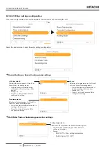
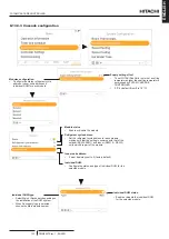
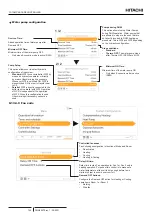
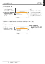
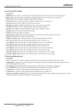
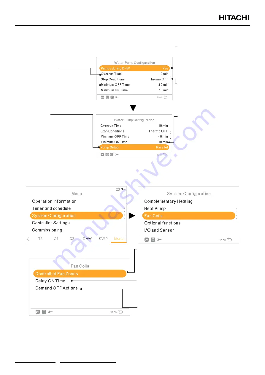
Water pump configuration

Minimum OFF Time: 

Minimum time of the water pump OFF.

• 

Only when Economic mode is active (DSW)

• 

Minimum ON Time: 

Minimum time of the water pump ON.

• 

Only when Economic mode is active 

(DSW)

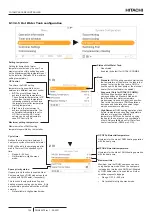
Pumps during DHW: 

This option allows to stop Water Pumps 

during DHW operation. Water pumps that 

are allowed to stop are the ones that are 

not directly involved to DHW heating-up 

procedure. This is WP2 and WP3 depending 

on the hydraulic configuration.

Overrun Time: 

Added operation time of water pump after 

Demand OFF.

Stop conditions: 

• 

Standard

• 

Thermo OFF: 

The water pump stops 

after Thermo OFF. (DSW5 pin 4 ON).

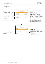
Pump Setup: 

This option allows user to select hydraulic 

configuration of the system.

• 

Standard:

 WP2 is connected after WP3 by 

means an hydraulic separator or directly 

by means Hitachi mixing kit accessory. 

Whenever WP2 is switched ON, WP3 is 

also switched ON in order to transfer heat 

to C2

• 

Parallel:

 WP2 is directly connected to the 

buffer tank in parallel with WP3. Operation 

of WP3 is independent of the operation 

of WP2. When this configuration is used, 

Hitachi mixing kit accessory cannot be 

used.

2 / 2

1 / 2

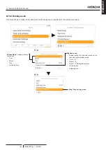
8.13.3.9  Fan coils

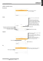
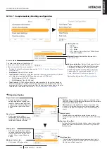
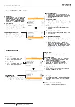
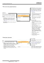
Demand OFF Actions: 

Configure the Demand OFF action for Heating or Cooling 

operation in Room 1 or Room 2.

•  Nothing
•  Stop fan

Controlled fan zones: 

Fan coil usage assignation in function of Mode and Room.

•  Deactivated
•  Heating
•  Cooling
• 

Heating & Cooling

Delay ON time: 

Delay time to start Fan operation for Fan 1 or Fan 2 only in 

heating operation. Purpose of this control is to make sure 

water temperature at fan coil is hot enough before fan is 

started in order to ensure user comfort.

YUTAKI CASCADE CONTROLLER

PMML0575 rev.1 - 09/2021

142

Summary of Contents for ATW-YCC-03

Page 1: ... MANUAL MANUAL DE INSTALACIÓN Y FUNCIONAMIENTO INSTALLATIONS UND BETRIEBSHANDBUCH MANUEL D INSTALLATION ET DE FONCTIONNEMENT MANUALE DI INSTALLAZIONE E D USO EN ES DE FR IT MANUAL DE INSTALAÇÃO E FUNCIONAMENTO MONTERINGS OG DRIFTSVEJLEDNING INSTALLATIE EN BEDIENINGSHANDLEIDING INSTALLATION OCH DRIFTHANDBOK ΕΓΧΕΙΡΙΔΙΟ ΕΓΚΑΤΑΣΤΑΣΗΣ ΚΑΙ ΛΕΙΤΟΥΡΓΙΑΣ PT DA NL SV EL PMML0575 rev 1 09 2021 ...

Page 2: ......

Page 3: ...ile per eventuali errori di stampa che esulano dal proprio controllo Português As especificações apresentadas neste manual estão sujeitas a alterações sem aviso prévio de modo a que a Hitachi possa oferecer aos seus clientes da forma mais expedita possível as inovações mais recentes Apesar de serem feitos todos os esforços para assegurar que todas as especificações apresentadas são correctas quais...

Page 4: ...sull ambiente e sulla salute e favorisce il riciclo dei materiali di cui è composta l apparecchiatura Non tentate di smontare il sistema o l unità da soli poichè ciò potrebbe causare effetti dannosi sulla vostra salute o sull ambiente Vogliate contattare l installatore il rivenditore o le autorità locali per ulteriori informazioni Lo smaltimento abusivo del prodotto da parte dell utente può compor...

Page 5: ... Nota Importante de acordo com o nome do modelo verifique o tipo da sua bomba de calor e a respetiva abreviatura e menção neste manual de instruções Este manual de instalação e de funcionamento está relacionado com unidades YUTAKI MODELKODIFICERING Vigtig information Kontrollér venligst din varmepumpetype i henhold til modelnavnet hvordan den forkortes og hvilken reference den har i denne vejledni...

Page 6: ......

Page 7: ... Split system R32 Outdoor unit 5 1 3 2 2 Split system R410A Outdoor unit 5 1 3 2 3 Split system Indoor unit 6 1 3 2 4 Complementary system 7 2 GENERAL SAFETY NOTES 8 2 1 Additional information about safety 8 2 2 Important notice 8 3 ELECTRICAL DATA 9 3 1 Considerations 9 3 2 Split system R410A Outdoor unit 10 3 3 Split system R32 Outdoor unit 10 3 4 Split system Indoor unit 11 3 4 1 YUTAKI S 11 3 ...

Page 8: ...5 3 Water piping 27 5 3 1 Water piping length 27 5 3 2 Water piping size 27 5 3 3 Water quality 28 5 3 4 Water flow control 28 6 ELECTRICAL AND CONTROL SETTINGS 29 6 1 General check 29 6 2 Electrical connection 31 6 2 1 Wiring size 31 6 2 2 Minimum requirements of the protection devices 34 6 3 Terminal board connections 36 6 3 1 Table board 1 36 6 3 2 Table board 2 36 7 UNIT CONTROLLER 49 7 1 Defi...

Page 9: ...ter Tank configuration 89 7 13 4 5 Swimming Pool configuration 91 7 13 4 6 Complementary Heating configuration 92 7 13 4 7 Heat Pump configuration 94 7 13 4 8 Fan coils 96 7 13 4 9 Optional functions configuration 97 7 13 4 10 Inputs Outputs and Sensors configuration 101 7 13 5 Holiday mode 103 7 13 6 Controller settings 104 7 13 7 Commissioning 105 7 13 8 About 105 7 13 9 Factory reset 106 7 13 1...

Page 10: ...uration 134 8 13 3 5 Hot Water Tank configuration 136 8 13 3 6 Swimming Pool configuration 138 8 13 3 7 Complementary Heating configuration 139 8 13 3 8 Heat Pump configuration 141 8 13 3 9 Fan coils 142 8 13 3 10 Optional functions configuration 143 8 13 3 11 Inputs Outputs and Sensors configuration 147 8 13 4 Holiday mode 149 8 13 5 Controller settings 150 8 13 6 Commissioning 151 8 13 7 About 1...

Page 11: ... energy for heating this provides savings of up to 80 on heating expenses compared to a traditional fossil fuel boiler The new YUTAKI series based on state of the art technology does not only achieve an outstanding performance in space heating but also provides domestic hot water with high efficiency Additionally cooling operation for summer can also be provided installing the dedicated Cooling ki...

Page 12: ...e configuration Radiator heating floor or both 2nd temperature area Domestic hot water production YUTAKI models also give the option of domestic hot water production allowing the user to benefit from the heat pump s high efficiency and achieve domestic hot water This is made possible by a domestic hot water tank In case of YUTAKI S COMBI the domestic hot water tank is built in the indoor unit For ...

Page 13: ...se instructions into account could lead to serious very serious or even fatal injuries to you and others In the texts following the danger symbol you can also find information on safety procedures during unit installation CAUTION The text following this symbol contains information and instructions relating directly to your safety Not taking these instructions into account could lead to minor injur...

Page 14: ...dium Low temperature Position separating hyphen fixed Compressor power of the combined outdoor unit HP 2 0 2 5 3 0 4 0 5 0 6 0 8 0 10 0 N R410A refrigerant R R32 refrigerant 1 series Made in Europe RWM X X X 1 E YUTAKI S COMBI Unit type YUTAKI S COMBI Split system Dual water module Indoor unit Domestic hot water tank Medium Low temperature Position separating hyphen fixed Compressor power of the c...

Page 15: ...ting hyphen fixed Language pack ATW YCC 03 1 3 2 Product list 1 3 2 1 Split system R32 Outdoor unit 1 230V 50Hz RAS 2WHVRP1 RAS 2 5WHVRP1 RAS 3WHVRP1 1 3 2 2 Split system R410A Outdoor unit 1 230V 50Hz 3N 400V 50Hz RAS 4WHVNPE RAS 4WHNPE RAS 5WHVNPE RAS 5WHNPE RAS 6WHVNPE RAS 6WHNPE RAS 8WHNPE RAS 10WHNPE GENERAL INFORMATION PMML0575 rev 1 09 2021 5 ...

Page 16: ...oling operation refer to the Cooling kit accessory for YUTAKI S units YUTAKI S COMBI NOTE Icons between brackets means possible extra operations to the factory supplied operations For cooling operation refer to the Cooling kit accessory for YUTAKI S COMBI units Standard model 1 230V 50Hz 3N 400V 50Hz RWD 2 0RW1E 220S RWD 2 0RW1E 220S RWD 2 5RW1E 220S RWD 2 5RW1E 220S RWD 3 0RW1E 220S RWD 3 0RW1E 2...

Page 17: ...2 5RW1E 220S K RWD 2 5RW1E 220S K RWD 3 0RW1E 220S K RWD 3 0RW1E 220S K RWD 4 0NW1E 220S K RWD 4 0NW1E 220S K RWD 5 0NW1E 220S K RWD 5 0NW1E 220S K RWD 6 0NW1E 220S K RWD 6 0NW1E 220S K 1 3 2 4 Complementary system YUTAKI CASCADE CONTROLLER ATW YCC 03 GENERAL INFORMATION PMML0575 rev 1 09 2021 7 ...

Page 18: ...OM CAREFULLY BEFORE STARTING TO WORK ON THE INSTALLATION OF THE AIR TO WATER HEAT PUMP SYSTEM Failure to observe the instructions for installation use and operation described in this documentation may result in operating failure including potentially serious faults or even the destruction of the air to water heat pump system Verify in accordance with the manuals which appear in the outdoor and ind...

Page 19: ...aximum current shown in the above table is the maximum total unit running current at the following conditions Supply voltage 90 of the rated voltage Unit capacity 100 at maximum operating conditions The power supply cables must be sized to cover this maximum current value Specifications in these tables are subject to change without notice in order that Hitachi may bring the latest innovations to t...

Page 20: ... 440 360 3 4 2 11 3 4 2 12 14 8 70 RAS 5WHNPE 4 6 2 87 4 6 2 90 14 8 70 RAS 6WHNPE 5 8 3 65 5 5 3 43 16 9 95 RAS 8WHNPE 7 1 4 41 7 3 4 58 24 15 00 RAS 10WHNPE 9 8 6 15 8 8 5 51 24 15 00 3 3 SPLIT SYSTEM R32 OUTDOOR UNIT RAS 2 3 WHVRP1 in combination with YUTAKI S YUTAKI S COMBI Model Power supply Applicable voltage Compressor and fan motors MC A Max IPT kW Cooling Heating U max V U min V RNC A IPT...

Page 21: ... 50Hz 440 360 Without electric heater 0 6 0 06 0 6 0 06 With electric heater 4 8 3 06 5 0 3 06 With DHW tank heater 4 5 3 06 13 7 3 06 With electric and DHW tank heaters 8 9 6 06 18 0 6 06 RWM 4 0 6 0 N1E 1 230V 50Hz 253 207 Without electric heater 0 6 0 08 0 7 0 08 With electric heater 26 7 6 08 26 7 6 08 With DHW tank heater 13 7 3 08 13 7 3 08 With electric and DHW tank heaters 39 8 9 08 39 8 9...

Page 22: ...ter 0 6 0 06 0 63 0 06 With electric heater 13 7 3 06 13 7 3 06 With DHW tank heater 12 6 2 81 12 6 2 81 With electric and DHW tank heaters 25 6 5 81 25 6 5 81 RWD 2 5 3 0 RW1E 220S K 3N 400V 50Hz 440 360 Without electric heater 0 6 0 06 0 63 0 06 With electric heater 8 7 3 06 9 3 3 06 With DHW tank heater 12 5 2 81 12 6 2 81 With electric and DHW tank heaters 12 5 5 81 12 6 5 81 RWD 4 0 6 0 NW1E ...

Page 23: ...2 R410A TEMPERATURE WORKING RANGE MODEL 2 0HP 2 5HP 3 0HP 4 0HP 5 0HP 6 0HP 8 0HP 10 0HP Water temperature ºC Refer to the graphics for each case Indoor ambient temperature 5 30 4 2 1 Space heating YUTAKI S S COMBI 2 0 3 0 HP Water outlet temperature ºC Ambient temperature ºC DB 6 60 Continuous working range Operation not possible Starting heat pump Back up heater Starting Heat Pump Starting only ...

Page 24: ...if back up heater is enabled 4 2 2 DHW For YUTAKI S S COMBI 2 0 3 0 HP Water tank temperature ºC Ambient temperature ºC DB 75 35 5 46 Continuous working range Starting only Back up Heater operation Maximum setting temperature Minimum setting temperature NOTE In case of heating up the DHW tank with an outdoor ambient temperature lower than 5 ºC and without using the DHW electrical heater the settin...

Page 25: ...ut using the DHW electrical heater the setting temperature must not exceed the maximum value in the specified continuous working range 4 2 3 Swimming pool heating 2 0 3 0 HP Swimming pool water temperature ºC Ambient temperature ºC DB Continuous working range Maximum setting temperature Minimum setting temperature 4 0 10 0 HP Swimming pool water temperature ºC Ambient temperature ºC DB Continuous ...

Page 26: ...P Minimum water flow rate 1 m3 h 1 0 1 1 1 2 2 0 2 2 Maximum water flow rate 1 m3 h 2 9 3 0 3 0 4 5 4 6 Minimum installation water volume 2 l 38 46 55 76 79 Minimum allowable water pressure MPa 0 1 Maximum allowable water pressure MPa 0 3 YUTAKI S COMBI MODEL 4 0 HP 5 0 HP 6 0 HP Minimum water flow rate 1 m3 h 1 0 1 1 1 2 Maximum water flow rate 1 m3 h 2 7 2 8 2 8 Minimum installation water volume...

Page 27: ...on water volume l 28 28 28 Minimum allowable water pressure MPa 0 1 Maximum allowable water pressure MPa 0 3 YUTAKI S COMBI MODEL 2 0 HP 2 5 HP 3 0 HP Minimum water flow rate 1 m3 h 0 5 0 6 0 6 Maximum water flow rate 1 m3 h 1 8 1 9 1 9 Minimum installation water volume l 28 28 28 Minimum allowable water pressure MPa 0 1 Maximum allowable water pressure MPa 0 3 WORKING RANGE PMML0575 rev 1 09 2021...

Page 28: ...um water flow of the indoor unit YUTAKI S 2 0 HP 2 5 HP Static pressure mwc 0 1 2 3 4 5 6 7 8 0 0 5 1 1 5 2 2 5 Static pressure mwc 0 1 2 3 4 5 6 7 8 0 0 5 1 1 5 2 2 5 Water flow m3 h Water flow m3 h 3 0 HP 4 0 HP Static pressure mwc 0 1 2 3 4 5 6 7 8 0 0 5 1 1 5 2 2 5 Static pressure mwc 0 1 2 3 4 5 6 7 8 0 0 5 1 1 5 2 2 5 3 3 5 Water flow m3 h Water flow m3 h WORKING RANGE PMML0575 rev 1 09 2021...

Page 29: ... 0 1 2 3 4 5 6 7 8 0 0 5 1 1 5 2 2 5 3 3 5 Water flow m3 h Water flow m3 h 8 0 HP 10 0 HP Static pressure mwc 0 1 2 3 4 5 6 7 8 9 0 0 5 1 1 5 2 2 5 3 3 5 4 4 5 5 Static pressure mwc 0 1 2 3 4 5 6 7 8 9 0 0 5 1 1 5 2 2 5 3 3 5 4 4 5 5 Water flow m3 h Water flow m3 h WORKING RANGE PMML0575 rev 1 09 2021 19 ...

Page 30: ...ow m3 h 3 0 HP 4 0 HP Static pressure mwc 0 1 2 3 4 5 6 7 8 0 0 5 1 1 5 2 2 5 3 Static pressure mwc 0 1 2 3 4 5 6 7 8 0 0 5 1 1 5 2 2 5 3 Water flow m3 h Water flow m3 h 5 0 HP 6 0 HP Static pressure mwc 0 1 2 3 4 5 6 7 8 0 0 5 1 1 5 2 2 5 3 Static pressure mwc 0 1 2 3 4 5 6 7 8 0 0 5 1 1 5 2 2 5 3 Water flow m3 h Water flow m3 h WORKING RANGE PMML0575 rev 1 09 2021 20 ...

Page 31: ...tional charge needed unit installation can achieve up to 30m 2 2 5HP 27m 3HP without any minimum floor area requirement 2HP 2 5HP 3HP Factory Charge kg 1 20 1 30 1 30 Charge less piping length m 10 10 10 Additional Charge needed g m 15 15 30 Maximum piping m 30 30 27 Maximum total refrigerant charge kg 1 50 1 60 1 81 Minimum room area requirement Amin m2 No requirement is needed Minimum piping len...

Page 32: ...ng size Piping connection size of outdoor unit indoor unit Outdoor unit Refrigerant pipe Indoor Unit Model Piping length Pipe Connection size Between Outdoor unit and Indoor unit Pipe Connection size Gas pipe Liquid pipe Gas pipe Liquid pipe Gas pipe Liquid pipe 2HP 3 50m Ø 12 7 1 2 Ø 6 35 1 4 Ø 12 7 Ø 6 35 Ø 15 88 5 8 Ø 6 35 1 4 2 5HP 3 50m Ø 9 52 3 8 3HP 3 27m Ø 15 88 5 8 Ø 9 52 3 8 Ø 15 88 Ø 6 ...

Page 33: ...rt which is showing the applicable height difference according to piping length When outdoor unit is installed higher than indoor unit When outdoor unit is installed lower than indoor unit Height difference m Total length between outdoor unit and indoor unit H OU Model 4 6 HP 8 10 HP Maximum piping length between outdoor unit and indoor unit Lmax Actual piping length L 75 m 70 m Equivalent piping ...

Page 34: ...4 6 HP Ø 15 88 5 8 Ø 9 52 3 8 4 0 6 0 HP Ø 15 88 5 8 Ø 9 52 3 8 8 HP Ø 25 4 1 Ø 9 52 3 8 8 HP Ø 25 4 1 Ø 9 52 3 8 10 HP Ø 12 7 1 2 10 HP Ø 12 7 1 2 5 2 1 1 Refrigerant charge before shipment W0 kg YUTAKI S S COMBI Outdoor unit model W0 kg RAS 4WH V NPE 3 3 RAS 5 6 WH V NPE 3 4 RAS 8WHNPE 5 0 RAS 10WHNPE 5 3 REFRIGERANT AND WATER PIPING PMML0575 rev 1 09 2021 24 ...

Page 35: ...eakage occurs and gas fills a room it may cause suffocation The maximum permissible concentration of HFC gas according to EN378 1 is Refrigerant Maximum permissible concentration kg m3 R410A 0 44 The minimum volume of a closed room where the system is installed to avoid suffocation in case of leakage is System combination Minimum volume m3 YUTAKI S S COMBI 4 HP 7 5 5 6 HP 7 8 YUTAKI S 8 HP 11 4 10...

Page 36: ... displacement volume 5 7 m3 h R410A or 14 4 m3 h R134a of the air conditioning system using the refrigerant Model Tonnes RAS 4 6 WH V NPE 2 27 RAS 8WHNPE 3 16 RAS 10WHNPE 4 11 NOTE Always take the maximum value between the R410A and R134a 4 Pay special attention to the place such as a basement etc where the refrigerant can stay since refrigerant is heavier than air Example Outdoor unit RAS 5WHVNPE...

Page 37: ...onnection Inlet connection Outlet connection Shut off valves 2 0 3 0 HP G 1 female G 1 female G 1 male G 1 male 4 0 10 0 HP G 1 1 4 female G 1 1 4 female G 1 1 4 male G 1 1 4 male YUTAKI S COMBI inches Model Space heating connection DHW connection Inlet connection Outlet connection Shut off valves Inlet connection Outlet connection Pressure and temperature relief valve 2 0 3 0 HP G 1 female G 1 fe...

Page 38: ...standard water quality Item DHW space Tendency 1 Water supplied 3 Corrosion Deposits of scales Electrical Conductivity mS m 25 C µS cm 25 C 2 100 2000 Chlorine Ion mg CI I max 250 Sulphate mg l max 250 Combination of chloride and sulphate mg l max 300 Total Hardness mg CaCO3 I 60 150 NOTE 1 The mark in the table means the factor concerned with the tendency of corrosion or deposits of scales 2 The ...

Page 39: ...0 25 RAS 5WHVNPE 0 25 RAS 6WHVNPE 0 25 RAS 4WHNPE 3N 400V 50Hz RAS 5WHNPE RAS 6WHNPE RAS 8WHNPE RAS 10WHNPE Split system R32 Outdoor unit Model Power supply Zmax Ω RAS 2WHVRP1 1 230V 50Hz RAS 2 5WHVRP1 RAS 3WHVRP1 0 43 Split system Indoor unit YUTAKI S Model Power supply Operation mode Zmax Ω RWM 2 0 3 0 R1E 1 230V 50Hz Without electric heater With electric heater With DHW tank heater With electri...

Page 40: ...oor unit Indoor unit YUTAKI S YUTAKI S COMBI Equipment complying with EN 61000 3 2 Professional use RAS 2WHVRP1 RAS 2 5WHVRP1 RAS 3WHVRP1 RAS 4WHNPE RAS 5WHNPE RAS 6WHNPE RWM 2 0R1E RWM 2 5R1E RWM 3 0R1E RWM 4 0N1E 3N RWM 5 0N1E 3N RWM 6 0N1E 3N RWM 8 0N1E RWM 10 0N1E Equipment complying with EN 61000 3 12 RAS 4WHVNPE RAS 5WHVNPE RAS 6WHVNPE RWM 4 0N1E 1 RWM 5 0N1E 1 RWM 6 0N1E 1 RWD 2 0RW1E 220S ...

Page 41: ...gnation 60245 IEC 57 Split system R410A Outdoor unit Model Power supply Max current A Power supply cables Transmitting cables Actuator cables EN60335 1 EN60335 1 EN60335 1 RAS 4WHVNPE 1 230V 50Hz 30 2 x 6 0 mm2 GND 2 x 0 75 mm2 Shielded cable 2 x 0 75 mm2 GND RAS 5WHVNPE 30 2 x 6 0 mm2 GND RAS 6WHVNPE 30 2 x 6 0 mm2 GND RAS 4WHNPE 3N 400V 50Hz 14 4 x 2 5 mm2 GND RAS 5WHNPE 14 4 x 2 5 mm2 GND RAS 6...

Page 42: ... 0 mm GND RWM 4 0 6 0 N1E 1 230V 50Hz Without electric heaters 0 7 2 x 0 75 mm GND With electric heater 26 7 2 x 6 0 mm GND With DHW tank heater 13 7 2 x 2 5 mm GND With electric and DHW tank heaters 39 8 2 x 10 0 mm GND 3N 400V 50Hz Without electric heaters 0 7 4 x 0 75 mm GND With electric heater 9 3 4 x 2 5 mm GND With DHW tank heater 13 7 4 x 2 5 mm GND With electric and DHW tank heaters 22 4 ...

Page 43: ...z Without electric heaters 0 63 4 x 0 75 mm GND With electric heater 9 3 4 x 2 5 mm GND With DHW tank heater 12 6 4 x 2 5 mm GND With electric and DHW tank heaters 12 6 4 x 2 5 mm GND RWD 4 0 6 0 NW1E 220S K 1 230V 50Hz Without electric heaters 0 65 2 x 0 75 mm GND With electric heater 26 7 2 x 6 0 mm GND With DHW tank heater 12 6 2 x 2 5 mm GND With electric and DHW tank heaters 38 7 2 x 10 0 mm ...

Page 44: ...er RCCB The Circuit Breakers CB are also known as Thermal Magnetic Circuit Breakers or just Magnetic Circuit Breakers MCB Split system R410A Outdoor unit Model Power supply Applicable voltage MC A CB A ELB nº of poles A mA U max V U min V RAS 4WHVNPE 1 230V 50Hz 253 207 30 32 2 40 30 RAS 5WHVNPE 30 32 RAS 6WHVNPE 30 32 RAS 4WHNPE 3N 400V 50Hz 440 360 14 15 4 40 30 RAS 5WHNPE 14 15 RAS 6WHNPE 16 20...

Page 45: ...ter 14 20 With DHW tank heater 14 20 With electric and DHW tank heaters 27 30 NOTE The data corresponding to DHW tank heater is calculated in combination with the domestic hot water tank accessory DHWT 200 300 S 3 0H2E YUTAKI S COMBI Model Power supply Applicable voltage Operation mode MC A CB A ELB nº of poles A mA U max V U min V RWD 2 0 3 0 RW1E 220 K 1 230V 50Hz 253 207 Without electric heater...

Page 46: ...G 02 ATW KNX 02 and ATW MBS 02 1 1 2 2 Indoor unit Outdoor unit ATW RTU Central Devices Use twist pair wires 0 75 mm for operation wiring between outdoor unit and indoor unit The wiring must consist of 2 core wires Do not use wire with more than 3 cores Use shielded wires for intermediate wiring to protect the units from noise interference with a length of less than 300 m and a size in compliance ...

Page 47: ...or unit table board as shown in the next picture 1 2 1 2 H LINK ATW RTU PC ARFH2E connection In cases where another PC ARFH2E must be connected as a second thermostat the connections between PC ARFH2E and the indoor unit must be done in terminals 3 and 4 and the connection of the power supply in terminals 28 29 as it is shown in the next picture 3 4 A B RCS H LINK PC ARFH2E OK DHWT Thermistor TDHW...

Page 48: ...and circuit 2 and the same demand ON OFF is used for both of them remove the jumper between terminals 13 and 14 of the Terminal board 2 and connect the RF receiver as shown in the following picture Thermostat requirements Power supply 230V AC Contact voltage 230V 13 14 13 14 Jumper Common Line Demand ON OFF Receiver input 2 NOTE If wireless intelligent thermostat is selected optional ON OFF thermo...

Page 49: ...ar panel sensor The solar combination by input demand allows HSW to be heated by solar system when there is enough solar energy available The connection of this input signal has to be done between terminals 16 and 18 at TB2 Common Line SolarIN Input 4 16 18 Smart tariff Default for input 5 This function can be used to block or limit the heat pump It allows an external Smart switch device to switch...

Page 50: ...l Domestic Hot water tank security thermostat its connected to terminals 22 23 and this funcion is not available for circuit 1 Output terminals Default output functions Mixing valve for Circuit 2 The mixing valve is controlled to maintain the second heating temperature at the second heating temperature set point The control system decides how much to open or close the mixing valve to achieve the d...

Page 51: ... requirements Power supply 230V AC 50Hz Maximum running current 100mA Output terminals Optional output functions 3 Way valve for Swimming pool Default for Output 1 YUTAKI units can be used to heat the water of a swimming pool The signal is used on a 3 way motorized diverting valve and to provide control of supply water flow for the swimming pool This output is available when the function is enable...

Page 52: ...t for output 4 This output is used when solar mode is enabled from Unit controller and the temperature in the solar panel rises above the water temperature in the domestic hot water tank DHWT The connection between terminals 39 and 40 shall be closed in order to activate the dedicated water pump for solar panel combination 39 40 Solar out Output 4 ELECTRICAL AND CONTROL SETTINGS PMML0575 rev 1 09 ...

Page 53: ... the manual of the Wireless intelligent room thermostat The Intelligent receiver is connected to the indoor unit table board as shown in the next picture 1 2 1 2 H LINK ATW RTU 28 29 L N AUXILIARY POWER ATW RTU CENTRAL DEVICE Power supply 230V AC 50Hz PC ARFH2E connection In cases where another PC ARFH2E must be connected as a second thermostat the connections between PC ARFH2E and the indoor unit...

Page 54: ...cuit 2 and the same demand ON OFF is used for both of them remove the jumper between terminals 13 and 14 of the Terminal board 2 and connect the RF receiver as shown in the following picture Thermostat requirements Power supply 230V AC Contact voltage 230V 13 14 13 14 Jumper Common Line Demand ON OFF Receiver input 2 NOTE If wireless intelligent thermostat is selected optional ON OFF thermostat ha...

Page 55: ...ar panel sensor The solar combination by input demand allows HSW to be heated by solar system when there is enough solar energy available The connection of this input signal has to be done between terminals 16 and 18 at TB2 Common Line SolarIN Input 4 16 18 Smart tariff Default for input 5 This function can be used to block or limit the heat pump It allows an external Smart switch device to switch...

Page 56: ...Domestic Hot water tank security thermostat its connected to terminals 22 23 and this funcion is not available for circuit 1 Output terminals Default output functions Mixing valve for Circuit 2 The mixing valve is controlled to maintain the second heating temperature at the second heating temperature set point The control system decides how much to open or close the mixing valve to achieve the des...

Page 57: ...be used to heat the water of a swimming pool The signal is used on a 3 way motorized diverting valve and to provide control of supply water flow for the swimming pool This output is available when the function is enabled from the Unit controller Using the appropriate wiring connect the valve cables as shown in the previous picture N M L 33 C Brown Black Blue 34 35 3WV SWP Output 1 Valve requiremen...

Page 58: ...t for output 4 This output is used when solar mode is enabled from Unit controller and the temperature in the solar panel rises above the water temperature in the domestic hot water tank DHWT The connection between terminals 39 and 40 shall be closed in order to activate the dedicated water pump for solar panel combination 39 40 Solar out Output 4 ELECTRICAL AND CONTROL SETTINGS PMML0575 rev 1 09 ...

Page 59: ...door unit software of version H 0114 and later 7 1 DEFINITION OF THE SWITCHES Liquid Crystal Display Screen where controller software is displayed OK button To select the variables to be edited and to confirm the selected values Arrows key It helps the user to move through the menus and views Run Stop button It works for all zones if none of the zones is selected or only for one zone when that zon...

Page 60: ...derogation from the configured timer Installer mode Informs that user controller is logged on the installer mode which has special privileges Menu lock It appears when menu is blocked from a central control When indoor communication is lost this icon disappears Holiday When some of the zones are set as holiday it has it s own holiday icon on their icons zone The holiday icon is also shown on the h...

Page 61: ...rced off Input is configured and its signal is received all the configured items C1 C2 DHW and or SWP are shown in OFF with this small icon below Auto ON OFF When daily average is over auto summer switch off temperature circuits 1 and 2 are forced to OFF Only if Auto ON OFF enabled Test Run Informs about the activation of the Test Run function Anti Legionella Activation of the Anti Legionella oper...

Page 62: ...led Deactivated Timer configuration Reset configuration Override Configuration Menu Contents Level 1 Level 2 Level 3 Level 4 Level 5 Type Until next action Specific time Forever Override duration Delete all timers configuration System Configuration Room Thermostats Setting temperature range air Air Eco Offset Thermostat Configuration Check RT address Compensation Factors Room Temp Demand OFF Water...

Page 63: ...Start Screed Drying About System Information Contact Information Factory Reset Lock the controller Return to user mode Installer mode Icon means that this menu is available only for installer a special user with higher access privileges to configure the system In order to access the controller as Installer go to Installer access menu After that the Enter password message is displayed The login pas...

Page 64: ... when the device acts as Room Thermostat only It does not control the unit Press OK button Select No when the device is not used as a room thermostat Select Yes in zone 1 Yes in zone 2 Yes in both zones depending on the number of circuits controlled When select Yes in both zones jump to screen 8 Press OK button Select the number of circuits 1 or 2 Press OK button Select the heat emitters on the ci...

Page 65: ...the bivalent point for boiler or electric backup heater from 20 ºC to 20 ºC Press OK button Select Yes if fan coil can be controlled through the outputs Press OK button Select the type of room thermostat installed in circuit 1 or 2 depending on the previous setting None wired or wireless Repeat this step in case of circuit 2 Press OK button Configuration assistant is completed Press OK button to g...

Page 66: ...he initial wizard Select Yes to launch the timer assistant for Room Thermostat 1 Press OK button If stay at home at weekend weedays the following patterns are applied Heating 6 30h 20ºC 22 30h 18ºC Cooling 6 30h 23ºC 22 30h 25ºC If senstive to cold is marked as Yes an offset of 1ºC is applied for heating UNIT CONTROLLER PMML0575 rev 1 09 2021 56 ...

Page 67: ... Circuit 1 Circuit 2 Questions Answers Is this device attached to the unit YES Is this device controlling the unit YES Is this device used as a Room Thermostat of a zone YES IN ZONE 1 YES IN ZONE 2 How many circuits do you have 2 Which are the heat emitters of circuit 1 Underfloor heating Which are the heat emitters of circuit 2 Underfloor heating Which are the cool emitters of circuit 1 Which are...

Page 68: ...ce controlling the unit YES Is this device used as a Room Thermostat of a zone YES IN ZONE 1 YES IN ZONE 2 How many circuits do you have 2 Which are the heat emitters of circuit 1 Underfloor heating Which are the heat emitters of circuit 2 Underfloor heating Which are the cool emitters of circuit 1 Which are the cool emitters of circuit 2 Do you have domestic hot water tank NO Do you have swimming...

Page 69: ...ch are the heat emitters of circuit 2 Underfloor heating Which are the cool emitters of circuit 1 Which are the cool emitters of circuit 2 Do you have domestic hot water tank NO Do you have swimming pool NO Do you have boiler NO Do you have electric backup heater NO COMPLETED NOTE After finishing Configuration assistant go to Input Outputs Sensor menu and select which auxiliary sensor do you want ...

Page 70: ...cuit 2 Underfloor heating Which are the cool emitters of circuit 1 Which are the cool emitters of circuit 2 Do you have domestic hot water tank NO Do you have swimming pool NO Do you have boiler NO Do you have electric backup heater NO COMPLETED NOTE After finishing Configuration assistant go to Input Outputs Sensor menu and select which auxiliary sensor do you want to use for ambient temperature ...

Page 71: ...it 2 Underfloor heating Do you have domestic hot water tank NO Do you have swimming pool NO Do you have boiler NO Do you have electric backup heater NO Which Thermostat do you have for Circuit 1 Wireless Which Thermostat do you have for Circuit 2 Wireless COMPLETED NOTE After finishing Configuration assistant proceed to wireless room thermostat binding procedure Refer to installation manual of roo...

Page 72: ...vice attached to the unit NO Is this device controlling the unit YES Is this device installed on a controlled zone YES ZONE 1 How many circuits do you have 2 Which are the heat emitters of circuit 1 Underfloor heating Which are the heat emitters of circuit 2 Underfloor heating Which are the cool emitters of circuit 1 Which are the cool emitters of circuit 2 Do you have swimming pool NO Do you have...

Page 73: ...ferent views Home Mode Room 1 if space is small it shows R1 Room 2 if space is small it shows R2 Circuit 1 if space is small it shows C1 Circuit 2 if space is small it shows C2 Fan 1 if space is small it shows F1 Fan 2 if space is smaill it shows F2 DHW SWP Menu UNIT CONTROLLER PMML0575 rev 1 09 2021 63 ...

Page 74: ...s are shown when pressing the OK button at the selected zone in comprehensive view or room thermostat view Room 1 2 Timer ECO Holiday If Zone is enabled Status Circuit 1 2 Timer ECO Holiday If Zone is enabled Status UNIT CONTROLLER PMML0575 rev 1 09 2021 64 ...

Page 75: ...k DHW Timer Boost If DHW is ON and Boost is availbable It can also be cancelled from quick actions Holiday If Zone is enabled Status Swimming Pool SWP Timer Holiday If Zone is enabled Status UNIT CONTROLLER PMML0575 rev 1 09 2021 65 ...

Page 76: ...will took them from the configured Rooms if no one is configured that temperature will not be displayed Outside temperature thermometer icon Water pressure indicator 7 6 1 Next schedule indication The indication of next schedule shows by priority Date of returning of absent mode Next schedule action If no derogation has been made shows next schedule action If derogation has been made it checks the...

Page 77: ...er on the left side If it has been enabled the auto mode it is also available here 7 8 ROOM 1 2 VIEW Room thermostats view displays Ambient Temperature of the room This temperature is got from controller or external sensor When editing it shows the setting temperature On right side it has zone notifications for Next timer action Eco and timer icons UNIT CONTROLLER PMML0575 rev 1 09 2021 67 ...

Page 78: ...oils Fan speeds Low Medium High and Auto Each fan has its independent on off 7 10 CIRCUIT 1 2 VIEW Circuit 1 or 2 view displays Water setting feedback When editing it shows the setting temperature On right side it has zone notifications for Next timer action Eco throughput summer switch off forced off and timer icons UNIT CONTROLLER PMML0575 rev 1 09 2021 68 ...

Page 79: ... Next timer action Boost throughput operating in comfort and timer icons During boost setting changed is the boost seeting 7 12 SWP VIEW SWP view displays Water setting feedback When editing if shows the setting temperature On right side it has zone notifications for Next timer action Throughput and timer icons UNIT CONTROLLER PMML0575 rev 1 09 2021 69 ...

Page 80: ...2 Hot Water Tank Swimming Pool Recent Status Register Table of the main variables of the system registered by steps of 5 minutes during 120min 1 4 Detailed information about DHW Operation Current temperature Only for YUTAKI S Top Sensor Only for YUTAKI S COMBI Bottom sensor Only for YUTAKI S COMBI Setting Temperature Electrical Heater Status Electrical Heater Operation Legionella Status Legionella...

Page 81: ... combination Operation Demand ON OFF Current temperature Setting temperature Detailed information about Solar combination Operation Demand ON OFF Solal Panel temperature Shows a list of the alarm history of the system 3 4 Detailed information about Communication status H Link H Link Central RCS Central Cascade Controller 4 4 UNIT CONTROLLER PMML0575 rev 1 09 2021 71 ...

Page 82: ...s only shown when defrosting TWO value is TWO HP when using a YUTAKI S COMBI or YUTAKI S otherwise it is normal TWO Water generation Considerations When operation status is COOL ON inlet pipe is orange outdoor pipe is blue When operaion status is HEAT ON SWP ON or DHW ON inlet pipe is blue outdoor pipe is orange otherwise pipe is in gray TWO value is TwoHP when using a YUTAKI S COMBI or YUTAKI S o...

Page 83: ...t are only shown when available on operation information exist wired or wireless thermostat for C1 The icon shown is defined on Room icon parameter under controller settings Circuit 2 Considerations When demand on inlet pipe is in orange outlet in blue When cooling inlet pipe is in blue outlet in orange If thermo off it is shown in gray Water pump 2 is shown if used Fan speed only shown when fan c...

Page 84: ...is shown indicating if it is being execute or not TWO is TWHP when using a YUTAKI S COMBI otherwise If buffer tank is located after DHW use Two if buffer tank is located before DHW use TWO3 Otherwise use Two Second sensor temperature shown only for YUTAKI S COMBI Swimming Pool Considerations When demand off inlet and outlet pipes are gray When demand on TWO water is orange hot and TWI water is blu...

Page 85: ...lays the main variables during the last hours Considerations Moving to left right variables shown change Moving up down we scroll through the registered time DWHT2 Only shown for YUTAKI S COMBI when not show DWHT1 and DWHT2 shown as when no tank is configured Icon Meaning Off Cool D OFF Cool T OFF Cool ON Heat D OFF Heat T OFF Heat ON DHW OFF Icon Meaning DHW ON SWP OFF SWP ON Alarm UNIT CONTROLLE...

Page 86: ...and electronics As an estimation this value may differ from real consumption measured by means an external power meter When power meter is used YUTAKI considers consumption read from pulse power meter Main view is a chart comparing total input power or total capacity depending on the menu By pressing right left it can be changed between zones Total Space Heating Space Cooling DHW Swimming Pool By ...

Page 87: ...ng right left it can be changed between zones Total Space Heating Space Cooling DHW Swimming Pool By pressing up down the different periods are shown By pressing OK or back we return to the chart view keeping the zone and comparison selected UNIT CONTROLLER PMML0575 rev 1 09 2021 77 ...

Page 88: ...imer to adjust the water working conditions for Circuit 1 2 Heating Cooling Air To set the timer to adjust the room temperature for Room 1 2 Only when using room thermostats Is possible to launch a timer assistant To set the timer to adjust the hot water tank temperature To set the timer to adjust the swimming pool temperature Press OK button to reset scheduled timers To set the Override type Unti...

Page 89: ... timer See explanation below Pressing the OK button with Timer Configuration being selected displays the detailed schedule screen The active schedule timers are shown in a weekly calendar Up to six timer events can be defined for each weekday and these can be used for turning the operation ON or OFF or to change the setting temperature Pressing the OK key with one of the weekdays being selected in...

Page 90: ... Timer assistant asks if user stays at home during weekend and weekdays If stay at home at weekend weekdays the followning patterns are applied Heating 6 30h 20ºC 22 30h 18ºC Cooling 6 30h 23ºC 22 30h 25ºC Timer assistant asks if user is sensistive to cold If senstive to cold is marked as Yes an offset of 1ºC is applied for heating UNIT CONTROLLER PMML0575 rev 1 09 2021 80 ...

Page 91: ...a schedule timer See explanation below Pressing the OK button with Timer Configuration being selected displays the detailed schedule screen The active schedule timers are shown in a weekly calendar Up to six timer events can be defined for each weekday and these can be used for turning the operation ON or OFF or operation mode ECO or Comfort Pressing the OK key with one of the weekdays being selec...

Page 92: ...ssing the OK button with Timer Configuration being selected displays the detailed schedule screen The active schedule timers are shown in a weekly calendar Up to six timer events can be defined for each weekday and these can be used for turning the operation ON or OFF or to change the setting temperature Pressing the OK key with one of the weekdays being selected in the weekly calendar screen disp...

Page 93: ... zone is done it is possible to override the timer configuration during a specific time Until next action derogation remains until next action of the timer Specific Time derogation status remains for the specified minutes Forever Derogation status is never released UNIT CONTROLLER PMML0575 rev 1 09 2021 83 ...

Page 94: ...nfiguration Compensation factors Room temperature demand OFF 1 3 Swimming Pool configuration Status Setting temperature Offset temperature Optional functions configuration Hydraulic separator Energy configuration Smart function Heating auto on off Auto heat cool Hot water tank Emergency operation I O and Sensor configuration Inputs Standard outputs Optional outputs Auxiliary sensors Complementary ...

Page 95: ...of the building rises in the case of low outdoor temperature and therefore the temperature of the supplied water becomes higher The room temperature compensation control allows to modify the water temperature determined by OTC control according to the setting room temperature and the actual room temperature In the case of heating if the difference between room temperature and setting temperature i...

Page 96: ...of the temperature for Circuit 1 or Circuit 2 heating or cooling mode Only when water calculation mode is Fix setting in Main device Circuit 1 or Circuit 2 must be ON to configure this setting Curve Selection of the gradient curve for Circuit 1 or Circuit 2 only for heating mode Only when water calculation mode is Gradient setting in Main device Range 0 2 2 2 Circuit 1 or Circuit 2 must be ON to c...

Page 97: ...r setting Configure the offset water temperature for the ECO mode for Space Heating or Space Cooling By using this function current water temperature setting is reduced by the indicated parameter Range 0 10 Mixing valve To control the second water temperature only for circuit 2 Values are adjusted for the use with the 2nd zone mixing kit accessory ATW 2KT 05 It is highly recommended not to change ...

Page 98: ...ht arrow keys Vertex offset High ambient temperature Low ambient temperature Set point at low ambient temperature Set point at high ambient temperature Gradient Configure the same variables as in the Points view but automatically User can only edit the gradient variable and it will automatically set the values for the other 4 variables on the chart Use the down arrow key to select the parameter to...

Page 99: ...water temperature measurement is done at higher tank position Due to this fact number of DHW operations decrease and its duration becomes longer which becomes more efficiency High Demand DHW heating operation starts if water temperature and setting temperature difference is larger than differential temperature DHW can be heated up using the heater the heat pump or a combination of both Only availa...

Page 100: ... 0 it means that heater will we switched ON after configured minutes since the moment HP has been switched ON 3 3 Smart Configuration Option to allow the tank to be heated to an intermediate temperature of comfort in conditions of water consumption in order to avoid heating to the traditional setting temperature Only available in Economic mode Comfort setting Intermediate target temperature of tan...

Page 101: ...tput 1 and sensor 2 See section 7 13 4 10 Inputs Outputs and Sensors configuration Offset temperature The setting temperature is increased by the indicated parameter Setting temperature Adjustment of the swimming pool water temperature setting Range 24 33 ºC UNIT CONTROLLER PMML0575 rev 1 09 2021 91 ...

Page 102: ... in Electrical heater Electrical heater Operation Starting Space Heating electric Heater is switched ON in case of low water temperature and low ambient temperature to provide extra capacity to HP Backup Space Heating Electric Heater is switched ON in case of low ambient temperature below Bivalent point in order to provide extra capacity to HP at coldest days of winter Bivalent point Electric heat...

Page 103: ...perature to allow solar operation Solar operation is allowed in case Panel temperature is ΔT connection ºC above tank temperature ΔT disconnection Allows to specify a difference temperature between tank and Panel temperature to stop solar operation Solar operation is not allowed in case Panel temperature is ΔT connection ºC below tank temperature Boiler combination Bivalent point Boiler is allowed...

Page 104: ...mand OFF cycles can be reduced by determining the time that must pass before accepting new Demand ON Seizure protection The pump seizure protection function prevents sticking of components due to long periods of inactivity by running the components during a short period every week Mixing valves and pumps are fully opened and then fully closed time depends on Mixing valve Run Time Factor Outdoor av...

Page 105: ... Time Added operation time of water pump after Demand OFF Stop conditions Standard Thermo OFF The water pump stops after Thermo OFF DSW5 pin 4 ON Pump Setup This option allows user to select hydraulic configuration of the system when hydraulic separator is used Standard WP2 is connected after WP3 by means an hydraulic separator or directly by means Hitachi mixing kit accessory Whenever WP2 is swit...

Page 106: ... for cooling operations Configure the Demand OFF action for Heating or Cooling operation in Room 1 or Room 2 Nothing Stop fan Controlled fan zones Fan coil usage assignation in function of Mode and Room Deactivated Heating Cooling Heating Cooling Delay ON time Delay time to start Fan operation for Fan 1 or Fan 2 only in heating operation Purpose of this control is to make sure water temperature at...

Page 107: ...witch OFF temperature See detailed information below Auto Heat Cool Allows to set automatic switch over to heating and cooling operation using the same daily average outdoor temperature of the previous day as in Heating auto ON OFF Smart function To block or limit the heat pump or increase demand due to electricity availability See detailed information on Smart function chapter 1 2 2 2 Hydraulic s...

Page 108: ...tem has been blocked due to HP Block Smart Action Check that Smart Act SG1 is set in input 5 see section 7 13 4 10 Inputs Outputs and Sensors configuration HP Block Heat Pump is forbidden in any condition Space Heating Cooling DHW when signal is active HP Limited A Limitation of power consumption up to a limit of x amperes to be set up in Limitation of amperage SG Ready The SG Grid is awarded to h...

Page 109: ...emperature Switch On Differential Differential temperature between average outdoor temperature of the previous day and the Switch Off temperature Auto Heat Cool Only available in units capable of heating and cooling operation and when cooling operation is enabled Switch to Heat temperature Operation switches to heating in case that the measured outdoor temperature value is lower than the threshold...

Page 110: ...circulation pump DHW Boost To force a one time heating of the DHW tank up to the temperature set as DHW Boost temperature This feature is useful to cover exceptional demand of DHW Trigger type Push favourite button Open NC or Closed NO Set input 6 for DHW Boost for trigger type open closed see section 7 13 4 10 Inputs Outputs and Sensors configuration Boost setting DHW temperature setting for the ...

Page 111: ...s circuit 1 in the installation Switch Circuit 1 to ECO mode when input is closed ECO C2 Switch Circuit 2 to ECO mode when input is closed Forced Off Forbid DHW space heating and space cooling Smart Act SG1 Fixed in input 5 if smart action is enabled To active Smart Function Swimming Pool Fixed in input 3 if swimming pool is enabled Consider Swimming pool in Demand ON when the signal is ON Solar F...

Page 112: ...Circuit 1 is set to Medium Fan 1 High Signal is active when fan coil speed selected for Circuit 1 is set to High Fan 2 Low Signal is active when fan coil speed selected for Circuit 2 is set to Low Fan 2 Medium Signal is active when fan coil speed selected for Circuit 2 is set to Medium Fan 2 High Signal is active when fan coil speed selected for Circuit 2 is set to High Constant Heating Signal is ...

Page 113: ...me back Holiday Mode Configure holiday come back Year Month Day Returning time Affected zones Enable switch off or disable switch on the zones during the holiday period Circuit 1 2 Room 1 2 Room 1 2 Setting temperature Hot water tank Swimming pool Start Stop holiday mode 1 2 2 2 UNIT CONTROLLER PMML0575 rev 1 09 2021 103 ...

Page 114: ... To apply an offset to the room temperature read by the in build sensor of the controller in order to match real room temperature Selection of the unit controller language Screen settings Display theme light dark auto Backlight time Backlight bright Contrast Brightness ON LED bright Beep on touch volume Display theme Light Dark Auto When Dark theme is selected background is changed to black text a...

Page 115: ... Start air purge Unit test run Duration Mode not available for heating only Start test run 7 13 8 About In this section of the LCD controller it is possible to find the following information System information Unit type Unit capacity Serial number Controller firmware Indoor PCB firmware Language package Refrigerant Contact information It is possible and recommendable to fill this information provi...

Page 116: ...stem The login password for the Installer is Right Down Left Right Press OK to confirm the password If the correct access code is entered the installer mode icon appears on the notifications bar bottom line After 30 minutes of inactivity it is necessary to repeat the log in process To exit the Installer mode and return to the unit menu go to the Return to user mode on the main menu UNIT CONTROLLER...

Page 117: ...function is only visible for the installer and allows to lock the menu in case of exhibition This action can also be launched from central When the controller is locked the lock icon appears insted the icon menu The password requested to unblock the controller is Right Down Left Right UNIT CONTROLLER PMML0575 rev 1 09 2021 107 ...

Page 118: ...rystal Display Screen where controller software is displayed OK button To select the variables to be edited and to confirm the selected values Arrows key It helps the user to move through the menus and views Run Stop button It works for all zones if none of the zones is selected or only for one zone when that zone is selected Return button To return to the previous screen YUTAKI CASCADE CONTROLLER...

Page 119: ...eekly timer Derogation When there is a derogation from the configured timer Installer mode Informs that user controller is logged on the installer mode which has special privileges Menu lock It appears when menu is blocked from a central control When indoor communication is lost this icon disappears Holiday When some of the zones are set as holiday it has it s own holiday icon on their icons zone ...

Page 120: ...Input is configured and its signal is received all the configured items C1 C2 DHW and or SWP are shown in OFF with this small icon below Auto ON OFF When daily average is over auto summer switch off temperature circuits 1 and 2 are forced to OFF Only if Auto ON OFF enabled Test Run Informs about the activation of the Test Run function Anti Legionella Activation of the Anti Legionella operation DHW...

Page 121: ...ext action Specific time Forever Override duration Menu Contents Level 1 Level 2 Level 3 Level 4 Level 5 Delete all timers configuration System Configuration Room Thermostats Setting temperature range air Air Eco Offset Thermostat Configuration Check RT address Compensation Factors Room Temp Demand OFF Water settings Space Heating Space Cooling Circuit 1 Circuit 2 DHW SWP Cascade configuration Sup...

Page 122: ...tion Factory Reset Lock the controller Return to user mode Installer mode Icon means that this menu is available only for installer a special user with higher access privileges to configure the system In order to access the controller as Installer go to Installer access menu After that the Enter password message is displayed The login password for the Installer is Right Down Left Right Press OK to...

Page 123: ...d with white icons Auto changes automatically to light at 08 00 am and turns to dark at 20 00 pm Configure circuit 1 and circuit 2 OTC Deactivated Points Gradient Fix Enable or disable DHW and Swimming Pool Select the heating source HP only HP EH HP Boiler Configure electrical heater use Starting or Backup Configure Boiler type Parallel or Serial Configure Solar Combination options Deactivated Inp...

Page 124: ... thermostat 1 or 2 None wired or wireless Check RT address if wired is selected Select Wireless binding ID 1 or 2 if wireless is selected Configure Fan coils Deactivated cooling heating or heat cool if wired is selected Select Wizard complete and press OK button Select Yes to complete the configuration Press OK button to go to the main screen YUTAKI CASCADE CONTROLLER PMML0575 rev 1 09 2021 114 ...

Page 125: ...t views Home Mode Room 1 if space is small it shows R1 Room 2 if space is small it shows R2 Circuit 1 if space is small it shows C1 Circuit 2 if space is small it shows C2 Fan 1 if space is small it shows F1 Fan 2 if space is smaill it shows F2 DHW SWP Menu YUTAKI CASCADE CONTROLLER PMML0575 rev 1 09 2021 115 ...

Page 126: ...shown when pressing the OK button at the selected zone in comprehensive view or room thermostat view Room 1 2 Timer ECO Holiday If Zone is enabled Status Circuit 1 2 Timer ECO Holiday If Zone is enabled Status YUTAKI CASCADE CONTROLLER PMML0575 rev 1 09 2021 116 ...

Page 127: ...Timer Boost If DHW is ON and Boost is availbable It can also be cancelled from quick actions Holiday If Zone is enabled Status Swimming Pool SWP Timer Holiday If Zone is enabled Status YUTAKI CASCADE CONTROLLER PMML0575 rev 1 09 2021 117 ...

Page 128: ...ook them from the configured Rooms if no one is configured that temperature will not be displayed Outside temperature thermometer icon Water pressure indicator 8 6 1 Next schedule indication The indication of next schedule shows by priority Date of returning of absent mode Next schedule action If no derogation has been made shows next schedule action If derogation has been made it checks the confi...

Page 129: ...the left side If it has been enabled the auto mode it is also available here 8 8 ROOM 1 2 VIEW Room thermostats view displays Ambient Temperature of the room This temperature is got from controller or external sensor When editing it shows the setting temperature On right side it has zone notifications for Next timer action Eco and timer icons YUTAKI CASCADE CONTROLLER PMML0575 rev 1 09 2021 119 ...

Page 130: ...Fan speeds Low Medium High and Auto Each fan has its independent on off 8 10 CIRCUIT 1 2 VIEW Circuit 1 or 2 view displays Water setting feedback When editing it shows the setting temperature On right side it has zone notifications for Next timer action Eco throughput summer switch off forced off and timer icons YUTAKI CASCADE CONTROLLER PMML0575 rev 1 09 2021 120 ...

Page 131: ...timer action Boost throughput operating in comfort and timer icons During boost setting changed is the boost seeting 8 12 SWP VIEW SWP view displays Water setting feedback When editing if shows the setting temperature On right side it has zone notifications for Next timer action Throughput and timer icons YUTAKI CASCADE CONTROLLER PMML0575 rev 1 09 2021 121 ...

Page 132: ...g temperature Mixing valve position only for circuit 2 1 3 Detailed information modules Operation status Water inlet temperature Water outlet temperature Individual DHW Enable or disable Type Main or Sub Detailed information about DHW Operation Current temperature Only for YUTAKI S Top Sensor Only for YUTAKI S COMBI Bottom sensor Only for YUTAKI S COMBI Setting Temperature Electrical Heater Status...

Page 133: ...rrect date and time before using the timer function Select the desired area to apply the timer function or delete all timers configuration Heating Cooling Water To set the timer to adjust the water working conditions for Circuit 1 2 Heating Cooling Air To set the timer to adjust the room temperature for Room 1 2 Only when using room thermostats Is possible to launch a timer assistant To set the ti...

Page 134: ...n Press OK button to reset scheduled timers Timer status Disable Enable Timer configuration New screen appears to configure a schedule timer See explanation below Pressing the OK button with Timer Configuration being selected displays the detailed schedule screen The active schedule timers are shown in a weekly calendar Up to six timer events can be defined for each weekday and these can be used f...

Page 135: ...assistant It is possible to set the timer for Room thermostats with a timer assistant When launching the timer assistant the current timer will be deleted Timer assistant asks if user stays at home during weekend and weekdays If stay at home at weekend weekdays the followning patterns are applied Heating 6 30h 20ºC 22 30h 18ºC Cooling 6 30h 23ºC 22 30h 25ºC YUTAKI CASCADE CONTROLLER PMML0575 rev 1...

Page 136: ...Timer assistant asks if user is sensistive to cold If senstive to cold is marked as Yes an offset of 1ºC is applied for heating YUTAKI CASCADE CONTROLLER PMML0575 rev 1 09 2021 126 ...

Page 137: ...edule timer See explanation below Pressing the OK button with Timer Configuration being selected displays the detailed schedule screen The active schedule timers are shown in a weekly calendar Up to six timer events can be defined for each weekday and these can be used for turning the operation ON or OFF or operation mode ECO or Comfort Pressing the OK key with one of the weekdays being selected i...

Page 138: ...the OK button with Timer Configuration being selected displays the detailed schedule screen The active schedule timers are shown in a weekly calendar Up to six timer events can be defined for each weekday and these can be used for turning the operation ON or OFF or to change the setting temperature Pressing the OK key with one of the weekdays being selected in the weekly calendar screen displays t...

Page 139: ...is done it is possible to override the timer configuration during a specific time Until next action derogation remains until next action of the timer Specific Time derogation status remains for the specified minutes Forever Derogation status is never released YUTAKI CASCADE CONTROLLER PMML0575 rev 1 09 2021 129 ...

Page 140: ...temperature demand OFF 1 3 Swimming Pool configuration Status Setting temperature Offset temperature Optional functions configuration Hydraulic separator Energy configuration Smart function Heating auto on off Auto heat cool Hot water tank Emergency operation I O and Sensor configuration Inputs Standard outputs Optional outputs Auxiliary sensors Complementary Heating configuration Heating Source H...

Page 141: ... building rises in the case of low outdoor temperature and therefore the temperature of the supplied water becomes higher The room temperature compensation control allows to modify the water temperature determined by OTC control according to the setting room temperature and the actual room temperature In the case of heating if the difference between room temperature and setting temperature is larg...

Page 142: ...he temperature for Circuit 1 or Circuit 2 heating or cooling mode Only when water calculation mode is Fix setting in Main device Circuit 1 or Circuit 2 must be ON to configure this setting Curve Selection of the gradient curve for Circuit 1 or Circuit 2 only for heating mode Only when water calculation mode is Gradient setting in Main device Range 0 2 2 2 Circuit 1 or Circuit 2 must be ON to confi...

Page 143: ...ose the Main module number Refrigerant cycle address Set the refrigerant cycle address for each module making sure that the setting is common with that of the outdoor DSW4 RSW1 and indoor DSW15 RSW2 units which are part of the module Indoor unit address It must be always set to 0 factory default Individual DHW Configure the status and type of individual DHW for the selected module Supply setting o...

Page 144: ... Configure the offset water temperature for the ECO mode for Space Heating or Space Cooling By using this function current water temperature setting is reduced by the indicated parameter Range 0 10 Mixing valve To control the second water temperature only for circuit 2 Values are adjusted for the use with the 2nd zone mixing kit accessory ATW 2KT 05 It is highly recommended not to change these val...

Page 145: ... arrow keys Vertex offset High ambient temperature Low ambient temperature Set point at low ambient temperature Set point at high ambient temperature Gradient Configure the same variables as in the Points view but automatically User can only edit the gradient variable and it will automatically set the values for the other 4 variables on the chart Use the down arrow key to select the parameter to m...

Page 146: ...perature measurement is done at higher tank position Due to this fact number of DHW operations decrease and its duration becomes longer which becomes more efficiency High Demand DHW heating operation starts if water temperature and setting temperature difference is larger than differential temperature DHW can be heated up using the heater the heat pump or a combination of both Only available when ...

Page 147: ...on Option to allow the tank to be heated to an intermediate temperature of comfort in conditions of water consumption in order to avoid heating to the traditional setting temperature Only available in Economic mode Comfort setting Intermediate target temperature of tank heating under water consumption conditions Comfort cycles Number of operations allowed to heat water to the comfort temperature A...

Page 148: ... sensor 2 see section 8 13 3 11 Inputs Outputs and Sensors configuration Offset temperature The setting temperature is increased by the indicated parameter Setting temperature Adjustment of the swimming pool water temperature setting Range 24 33 ºC YUTAKI CASCADE CONTROLLER PMML0575 rev 1 09 2021 138 ...

Page 149: ...n Electrical heater See detailed information in Electrical heater Electrical heater Operation Starting Space Heating electric Heater is switched ON in case of low water temperature and low ambient temperature to provide extra capacity to HP Backup Space Heating Electric Heater is switched ON in case of low ambient temperature below Bivalent point in order to provide extra capacity to HP at coldest...

Page 150: ...to allow solar operation Solar operation is allowed in case Panel temperature is ΔT connection ºC above tank temperature ΔT disconnection Allows to specify a difference temperature between tank and Panel temperature to stop solar operation Solar operation is not allowed in case Panel temperature is ΔT connection ºC below tank temperature Boiler combination Bivalent point Boiler is allowed to opera...

Page 151: ...ass before accepting new Demand ON Seizure protection The pump seizure protection function prevents sticking of components due to long periods of inactivity by running the components during a short period every week Mixing valves and pumps are fully opened and then fully closed time depends on Mixing valve Run Time Factor Outdoor average temperature OTC average is used to neutralise the effect of ...

Page 152: ...by means an hydraulic separator or directly by means Hitachi mixing kit accessory Whenever WP2 is switched ON WP3 is also switched ON in order to transfer heat to C2 Parallel WP2 is directly connected to the buffer tank in parallel with WP3 Operation of WP3 is independent of the operation of WP2 When this configuration is used Hitachi mixing kit accessory cannot be used 2 2 1 2 8 13 3 9 Fan coils ...

Page 153: ...ge outdoor temperature of the previous day is higher than the defined Switch OFF temperature See detailed information below Auto Heat Cool Allows to set automatic switch over to heating and cooling operation using the same daily average outdoor temperature of the previous day as in Heating auto ON OFF Smart function To block or limit the heat pump or increase demand due to electricity availability...

Page 154: ...warded to heat pump series This control technology integrates the system in a smart grid by using two digital inputs establishing an unidirectional connection See Service Manual for detailed information It is necessary to configure an input for SG2 DHW Block DHW Operation is forbidden when signal is active DHW only Heat pump operation for any condition except DHW is forbidden when signal is active...

Page 155: ...ature Switch On Differential Differential temperature between average outdoor temperature of the previous day and the Switch Off temperature Auto Heat Cool Only available in units capable of heating and cooling operation and when cooling operation is enabled Switch to Heat temperature Operation switches to heating in case that the measured outdoor temperature value is lower than the threshold for ...

Page 156: ...lation pump DHW Boost To force a one time heating of the DHW tank up to the temperature set as DHW Boost temperature This feature is useful to cover exceptional demand of DHW Trigger type Push favourite button Open NC or Closed NO Set input 6 for DHW Boost for trigger type open closed see section 8 13 3 11 Inputs Outputs and Sensors configuration Boost setting DHW temperature setting for the Boost...

Page 157: ...d Circuit 2 to ECO mode when input is closed ECO C1 by default in input 2 if there is circuit 1 in the installation Switch Circuit 1 to ECO mode when input is closed ECO C2 Switch Circuit 2 to ECO mode when input is closed Forced Off Forbid DHW space heating and space cooling Smart Act SG1 Fixed in input 5 if smart action is enabled To active Smart Function Swimming Pool Fixed in input 3 if swimmi...

Page 158: ...an 1 High Signal is active when fan coil speed selected for Circuit 1 is set to High Fan 2 Low Signal is active when fan coil speed selected for Circuit 2 is set to Low Fan 2 Medium Signal is active when fan coil speed selected for Circuit 2 is set to Medium Fan 2 High Signal is active when fan coil speed selected for Circuit 2 is set to High Constant Heating Signal is active in case operation mod...

Page 159: ...ck Holiday Mode Configure holiday come back Year Month Day Returning time Affected zones Enable switch off or disable switch on the zones during the holiday period Circuit 1 2 Room 1 2 Room 1 2 Setting temperature Hot water tank Swimming pool Start Stop holiday mode 1 2 2 2 YUTAKI CASCADE CONTROLLER PMML0575 rev 1 09 2021 149 ...

Page 160: ...Adjust date and time European summer time Temp sensor offset Selection of the unit controller language Screen settings Display theme light dark auto Backlight time Backlight bright Contrast Brightness ON LED bright Beep on touch volume Display theme Light Dark Auto When Dark theme is selected background is changed to black text and icons to white When Auto theme is selected it changes automaticall...

Page 161: ... 13 7 About In this section of the LCD controller it is possible to find the following information System information Type Modules type System capacity Serial number Controller firmware Indoor PCB firmware Language package Refrigerant Contact information It is possible and recommendable to fill this information providing a contact phone to the user YUTAKI CASCADE CONTROLLER PMML0575 rev 1 09 2021 ...

Page 162: ...The login password for the Installer is Right Down Left Right Press OK to confirm the password If the correct access code is entered the installer mode icon appears on the notifications bar bottom line After 30 minutes of inactivity it is necessary to repeat the log in process To exit the Installer mode and return to the unit menu go to the Return to user mode on the main menu YUTAKI CASCADE CONTR...

Page 163: ...ion is only visible for the installer and allows to lock the menu in case of exhibition This action can also be launched from central When the controller is locked the lock icon appears insted the icon menu The password requested to unblock the controller is Right Down Left Right YUTAKI CASCADE CONTROLLER PMML0575 rev 1 09 2021 153 ...

Page 164: ...nected broken or short circuited connector 14 o o Indoor Indoor Gas Pipe Temperature Thermistor Abnormality THMg Loose disconnected broken or short circuited connector 15 o o Indoor Water Circuit 2 thermistor abnormally THMwo2 Loose disconnected broken or short circuited connector 16 o o Indoor Water DHW thermistor abnormally THMdhwt Loose disconnected broken or short circuited connector 17 o o In...

Page 165: ...therm Hlink communication for a continuous period of 10 minutes 78 o o Indoor LCD RF Communication failure There is no communication for 1 hour with on or two RF receives which are bound to the RF Bridge 79 o o Indoor outdoor Unit Capacity setting Error There is no concordance between indoor outdoor unit capacity 80 o o Indoor LCD H link RCS transmission error No H link communication for a continu...

Page 166: ...on for Mixed circuit Circuit 2 supply temperature Target temperature offset 74 P74 Indoor Unit over temperature limit protection Two Tmax 5K 75 Indoor Freeze Protection by Cold water inlet outlet temperature detection 77 Indoor LCD Receiver Communication failure No Opentherm Hlink communication for a continuous period of 10 minutes 78 Indoor LCD RF Communication failure There is no communication f...

Page 167: ...broken cable short circuit 21 High pressure sensor 22 Thermistor for outdoor ambient temperature THM7 24 Thermistor for evaporating temperature THM8 Incorrect Wiring Disconnected Wiring Wire Breaking Short Circuit Fan Motor Locking at Heating Operation 31 System Incorrect capacity setting or combined capacity between outdoor and indoor units Incorrect Capacity Code Setting Excessive or Insufficien...

Page 168: ...ss or refrigerant cycle Over 64 indoor units setting by number or indoor unit address b5 Incorrect setting of indoor unit number for H LINK type The number of indoor units connected to the H LINK II of one system is 17 or higher Alarms for LCD Alarm Code Retry Stop Code YUTAKI S SC Origin Detail of Abnormality Main Factors 202 o LCD Wrong settings of PC ARFH2E 203 o LCD Sub PC ARFH2E stops answeri...

Page 169: ...it system check the refrigerant pressure using the check joints of the outdoor unit 4 Cabinet Stain Check for any stain and remove it cleaning if it is the case Fixing screw Check for any loosened screw or any lost screw Fix the loosened screws and the lost screws Insulation material Check for any peeled thermal insulator on the cabinet Repair the thermal insulator 5 Electrical equipment Activatio...

Page 170: ...ecial attention to the water pipe connection placed over the electrical box 3 Water flow and pressure Water flow Space heating Check the water flow m3 h through the unit controller in the Heat Pump Details of the Operation Information menu DHW if used Check whether the water circulation is correct along all the DHW circuit Pressure checking Space heating Check the water pressure using the manomete...

Page 171: ...ions Normally Filter ball valve it is used as a shut off valve by turning the handle 90º clockwise 1 Filter ball valve makes the maintenance operations easier Once the valve is in closed position open the draining port tap 2 and by turning the handle up to 22º clockwise the water from the inlet is guided behind the filter and runs in opposite direction through the draining port 3 The water circuit...

Page 172: ...ctrical equipment Activation Check for an abnormal activation of the magnetic contactor the relay the PCBs and others Line condition Pay attention to the working voltage the working amperage and the working phase balance Check for any faulty contact that is caused by the loosened terminal connections the oxidized contacts the foreign matter and other items Check the electrical insulation resistanc...

Page 173: ...s been drained close again the drain port for indoor unit water CAUTION When draining the indoor unit water from its drain port the leaved water could be hot and could keep in pressure Perform the draining procedure carefully DHWT Drain Indoor unit Drain Draining of the DHW circuit 1 Switch OFF the main power supply of the indoor unit 2 Close the main DHW inlet valve water inlet shut off valve in ...

Page 174: ......

Page 175: ......

Page 176: ...n Johnson Controls Hitachi Air Conditioning Spain S A U Ronda Shimizu 1 Políg Ind Can Torrella 08233 Vacarisses Barcelona Spain Copyright 2021 Johnson Controls Hitachi Air Conditioning Spain S A U All rights reserved ...

Reviews: