– 5 –
AX-F300
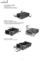
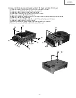
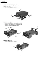
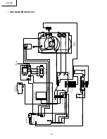
3. Removal of Rear Panel
(1) Remove 9 screws
from the rear panel.
(2) Remove the connector
.
4. Removal of Front P. W. Board
(1) Remove 2 screws
and then the tone P. W. board.
(2) Remove the volume knob assy, remove the nut and remove the volume P. W. board.
(3) Remove 9 screws
.
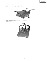
5. Removal of Main P. W. Board
(1) Lift up the TU P. W. board and remove it from the main P. W. board.
(2) Remove 2 screws
from the top side of the main P. W. board.
(3) Remove 4 screws
from the bottom side of the chassis.
(4) Remove the 4 P. W. board holders
from the chassis via the bottom side of the chassis.
TU P. W. board
Control
N u t
Summary of Contents for AXF300E
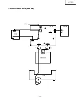
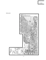
Page 14: ... 14 AX F300 PRINTED WIRING BOARDS AM FM TUNER AMPLIFIER HTA R100 MAIN PWB Component Side ...
Page 15: ... 15 AX F300 Soldering Side ...
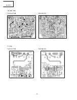
Page 16: ... 16 AX F300 PRE AMP PWB Component Side Soldering Side PT PWB Component Side Soldering Side ...
Page 18: ... 18 AX F300 DISPLAY PWB TU PWB Soldering Side Component Side Soldering Side Component Side ...
Page 20: ... 20 AX F300 MONITOR PWB PT PWB Component Side Soldering Side Soldering Side Component Side ...
Page 21: ... 21 AX F300 MINI DISC RECORDER HMD R50 MAIN PWB Component Side ...
Page 22: ... 22 AX F300 Soldering Side ...
Page 23: ... 23 AX F300 DISPLA Y PWB Component Side Soldering Side ...
Page 28: ... 28 AX F300 ...
Page 29: ...AX F300 29 30 31 CIRCUIT DIAGRAM AM FM TUNER AMPLIFIER HTA R100 ...
Page 30: ...AX F300 32 33 34 ...
Page 31: ...AX F300 35 36 37 ...
Page 32: ...AX F300 38 39 40 ...
Page 33: ...AX F300 41 42 43 CD CHANGER DA R100 ...
Page 34: ...AX F300 44 45 46 ...
Page 35: ...AX F300 47 48 49 MINI DISC RECORDER HMD R50 ...
Page 36: ......
Page 40: ...THE UPDATED PARTS LIST FOR THIS MODEL IS AVAILABLE ON ESTA ...

