background image

--- 13 ---

(4) Removal of the Handle Cover [45]

Remove the five Tapping Screws (W/Flange) D4 x 16 (Black) [46] to remove the Handle Cover [45].

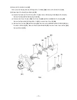
(5) Disassembly of the Gear [1] and Motor (B) [19]

(a) Remove the Seal Lock Flat Hd. Screw M5 x 12 [3] to remove the Bearing Holder [2] and the Gear [1].

     Remove the Gear [1] from the Bearing Holder [2].

(b) Remove Inner Cover (A) Ass'y [20], Inner Cover (B) [24] and Motor (B) [19] from the Housing [32].

     Remove the Nylock Bolt (W/Flange) M4 x 12 [25] to remove Inner Cover (B) [24].

(c) Remove the Lock Lever [22] and the Spring [33], then remove the Ball Bearing 609VVC2PS2L [23] from

     the pinion of Motor (B) [19].  Remove the two Special Bolts M5 [21] to remove Inner Cover (A) Ass'y [20].

     Remove Motor (B) [19].

[20]

[21]

[22]

[19]

[23]

[1]

[2]

[3]

[33]

[32]

[24]

[25]

Fig. 4

Summary of Contents for C 6DC2

Page 1: ...POWER TOOLS TECHNICAL DATA AND SERVICE MANUAL CORDLESS CIRCULAR SAW C 6DC2 SPECIFICATIONS AND PARTS ARE SUBJECT TO CHANGE FOR IMPROVEMENT LIST No F873 Jun 2002 C MODEL C 6DC2 ...

Page 2: ...AL DATA AND SERVICE MANUAL a symbol s is are used in the place of company name s and model name s of our competitor s The symbol s utilized here is are as follows Symbols Utilized Competitors Company Name Model Name MAKITA 5620DWA C ...

Page 3: ...INGLE CHARGE 6 8 PRECAUTIONS IN SALES PROMOTION 7 8 1 Handling Instructions 7 8 2 Caution Plates 9 8 3 Inherent Drawbacks of Cordless Circular Saws Requiring Particular Attention During Sales Promotion 10 9 REPAIR GUIDE 11 9 1 Precautions in Disassembly and Reassembly 11 9 2 Precautions in Disassembly and Reassembly of Battery Charger 18 10 STANDARD REPAIR TIME UNIT SCHEDULES 19 Assembly Diagram f...

Page 4: ... a 165 mm 6 1 2 saw blade capable of cutting a 2 x 4 piece of wood with a single pass of the blade even at an angle of 45 This feature is expected to make this product series stand out from the existing competitive models 3 APPLICATIONS Cutting various wood materials 4 SELLING POINTS Safety switch lever High capacity 2 0 Ah battery Electric brake Adjustable guide piece 90 fine adjustment screw und...

Page 5: ...C2 is the first product in the portable circular saw industry equipped with a spotlight for lighting blade edges The working efficiency is improved because the spotlight helps to align the saw blade with a premarked cutting line even in a dimly lit workplace Because the light switch and the safety switch lever are integrated into one switch the switch operation is easy and the spotlight can be lit...

Page 6: ... C 6DC2 is equipped with an adjustable guide piece that aligns a saw blade with a premarked cutting line When the guide piece become misadjusted simply loosen the fixing screw and relocate the guide piece to the proper position Guide piece ...

Page 7: ... C 140 F Indication method of battery charging function Nominal service life Nominal capacity Type of battery Nominal voltage Weight Main body including battery 3 3 kg 7 3 lbs Charger unit including cord 0 6 kg 1 3 lbs Main body charger case and other standard accessories 7 8 kg 17 lbs Net Gross Standard accessories Charger UC 24YFA 1 Saw blade 1 Box wrench 1 Guide 1 Plastic tool case 1 Charging d...

Page 8: ...meter 165 mm 6 1 2 Hole diameter 20 mm 25 32 No of teeth 40 pieces Code No 317452 For Australia and New Zealand Model EB 1820 2 0 Ah Code No 319763 Model EB 1820 2 0 Ah Code No 319762 External diameter 165 mm 6 1 2 165 mm 6 1 2 Hole diameter 15 9 mm 5 8 15 9 mm 5 8 No of teeth 16 pieces 40 pieces Code No 302407 317451 ...

Page 9: ...ess None 60 minutes 165 mm 6 1 2 57 mm 2 1 4 40 mm 1 9 16 40 pieces 2 000 mAh 3 400 Unable 18 V Equipped Equipped Aluminum die casting Equipped 50 minutes C 6DC2 Dimension Length No load noise level dB A Tool weight Height Width 364 mm 14 5 16 227 mm 9 197 mm 7 3 4 3 4 kg 7 5 lbs 75 dB 355 mm 14 247 mm 9 3 4 191 mm 7 1 2 3 3 kg 7 3 lbs 75 dB Model Model name Wood 2 x 4 Cuts 2 x 8 Cuts Concreteform...

Page 10: ... power outlet only Use of any other power source DC outlet fuel powered generator etc will cause the charger to overheat and burn out 4 Do not use any voltage increasing equipment transformer etc between the power source and the charger If the charger is used with voltage over and above that indicated on the unit it will not function properly 5 Conduct battery charging at an ambient temperature ra...

Page 11: ...ge battery and charger to permit rapid charging Incorrect parts replacement and or wiring will cause malfunctions which could result in fire or other hazard Instruct the customer to bring these units to an authorized service center in the event repair or replacement is necessary 10 Disposal of the Type Model 1820 battery Ensure that all customers understand that Model EB 1820 Batteries should be t...

Page 12: ...on Plates 1 The following basic safety precautions are listed on the Name Plate attached to the main body of each tool 3 The following cautions are listed on the Name Plate attached to each Model UC 24YFA Charger For the U S A and Canada For the U S A and Canada For Australia and New Zealand For the U S A ...

Page 13: ...o not twist or thrust the main body during cutting Otherwise the motor becomes locked and will cause burning of the motor or deterioration of the battery The motor must not be locked during operation 2 Avoid continuous heavy duty operation Cutting a thick workpiece with strong pressure can put a heavy load on the motor If such an operation is performed continuously the temperature of the motor and...

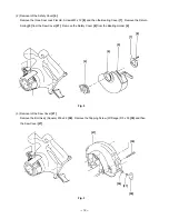
Page 14: ...n the Parts List and the exploded assembly diagram for the Model C 6DC2 9 1 1 Disassembly 1 Removal of the TCT Saw Blade 11 While pressing the Lock Lever 22 turn the Bolt W Washer M7 x 17 5 13 clockwise with the attached Box Wrench 10 mm 502 to fix the saw blade shaft Turn the Bolt W Washer M7 x 17 5 13 counterclockwise with the Box Wrench 10 mm 502 to loosen it Remove Washer B1 12 the TCT Saw Bla...

Page 15: ...the Bearing Cover 7 Remove the Return Spring 5 from the Saw Cover 27 Remove the Safety Cover 4 from the Bearing Holder 2 3 Removal of the Saw Cover 27 Remove the Bolt Ass y Square M6 x 22 59 Remove the Tapping Screw W Flange D5 x 50 30 and then the Saw Cover 27 Fig 2 Fig 3 4 5 7 2 8 36 30 27 37 59 ...

Page 16: ...he Gear 1 Remove the Gear 1 from the Bearing Holder 2 b Remove Inner Cover A Ass y 20 Inner Cover B 24 and Motor B 19 from the Housing 32 Remove the Nylock Bolt W Flange M4 x 12 25 to remove Inner Cover B 24 c Remove the Lock Lever 22 and the Spring 33 then remove the Ball Bearing 609VVC2PS2L 23 from the pinion of Motor B 19 Remove the two Special Bolts M5 21 to remove Inner Cover A Ass y 20 Remov...

Page 17: ... 14 6 Removal of the Base Ass y 63 Extract the Roll Pin D6 x 45 60 that connects the Base Ass y 63 and the Housing 32 Remove the Base Ass y 63 60 32 63 Fig 5 ...

Page 18: ...1 Reassembly of the components for power supply a Be sure to perform wiring connections as indicated in the wiring diagram Fig 9 18 19 48 17 49 47 41 39 40 38 52 54 18 51 53 50 51 18 Fig 6 Fig 7 b Mount Inner Cover A Ass y 20 to Motor B 19 as illustrated in Fig 7 Adjust the screw boss of Inner Cover A Ass y 20 to the hole of Motor B 19 19 20 ...

Page 19: ... Insert the lead wire into the groove After putting knob s convex in the hole of terminal A assemble into the housing Insert the groove portion of the terminal into the rib of the housing Terminal No 2 Groove Blue Black Terminal No 3 17 40 42 43 53 47 38 19 50 Red Terminal No 1 Brown Blue Convex Yellow 54 52 Blue Brown Groove 48 49 Mounting direction of Terminals 52 54 ...

Page 20: ... knob is operated b Check that the cutting and inclining operation of the Base Ass y 63 is smoothly performed c Check that the Safety Cover 4 operates smoothly d Check that the brake is applied when turning off the switch e Check that the saw blade turns in the arrow direction indicated on the saw cover counterclockwise viewed from the front of the saw blade f Check that runout of the saw blade is...

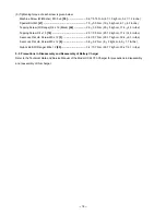
Page 21: ...crew D4 x 10 18 2 0 0 5 N m 20 5 kgf cm 17 4 4 3 in lbs Seal Lock Flat Hd Screw M5 x 12 3 3 4 0 7 N m 35 7 kgf cm 30 4 6 1 in lbs Seal Lock Flat Hd Screw M3 x 12 8 0 8 0 2 N m 8 2 kgf cm 6 9 1 7 in lbs Nylock Bolt W Flange M4 x 12 25 3 4 0 7 N m 35 7 kgf cm 30 4 6 1 in lbs 9 2 Precautions in Disassembly and Reassembly of Battery Charger Refer to the Technical Data and Service Manual of the Model U...

Page 22: ... Fixed Variable C 6DC2 Work Flow Saw Cover Gear Bearing Holder Ball Bearing 6002VV TCT Saw Blade Safety Cover Return Spring 60 min 50 Housing Motor B Base Ass y General Assembly Inner Cover A Ass y Ball Bearing 609VV Inner Cover B Lock Lever Switch Handle Cover ...

Page 23: ...SAW Model C 6DC2 2002 6 30 E1 F873 501 502 503 504 1 2 3 4 5 6 7 8 9 10 11 12 13 14 15 16 17 18 19 20 21 22 23 24 25 26 27 28 29 30 31 32 33 34 35 36 37 38 39 40 18 51 52 53 54 51 18 36 55 56 57 58 59 37 61 62 60 63 64 A A 41 42 43 44 45 46 47 48 49 50 ...

Page 24: ...EW D4X10 3 19 320 996 MOTOR B 1 20 318 347 INNER COVER A ASS Y 1 INCLUD 21 21 317 914 SPECIAL BOLT M5 2 22 317 194 LOCK LEVER 1 23 609 VVM BALL BEARING 609VVC2PS2L 1 24 317 195 INNER COVER B 1 25 317 196 NYLOCK BOLT W FLANGE M4X12 2 26 302 012 NUT M5 BLACK 1 27 317 201 SAW COVER 1 28 CAUTION PLATE 1 FOR USA CAN 29 HITACHI LABEL B 1 30 317 449 TAPPING SCREW W FLANGE D5X50 3 31 LABEL A 1 32 321 003 ...

Page 25: ...BLACK 1 56 321 006 GUIDE PIECE 1 57 307 898 WING BOLT M6X18 1 58 941 056 SPRING 1 59 314 620 BOLT ASS Y SQUARE M6X22 1 INCLUD 37 60 949 523 ROLL PIN D6X45 10 PCS 1 61 308 109 SLOTTED HD SET SCREW SEAL LOCK M6X8 1 62 314 621 BOLT ASS Y SQUARE M6X20 1 INCLUD 37 63 321 005 BASE ASS Y 1 INCLUD 36 55 58 61 62 64 319 763 BATTERY EB 1820 W ENGLISH N P 1 64 319 762 BATTERY EB 1820 W ENGLISH N P 1 FOR NZL ...

Page 26: ...IVE PARTS 4 ITEM NO CODE NO DESCRIPTION REMARKS NO USED 6 02 C 6DC2 STANDARD ACCESSORIES Printed in Japan 020630N 501 CHARGER MODEL UC 24YFA 1 502 940 543 BOX WRENCH 10MM 1 503 302 756 GUIDE 1 504 321 100 CASE 1 ...

Page 27: ......

Reviews: