--- 16 ---
9-2. Precautions in Disassembly and Reassembly of Battery Charger
Refer to the Technical Data and Service Manual of the Model UC 24YFB Charger for precautions in disassembly
and reassembly of this charger.
9-3. Mounting Method of Bevel Plate and Link
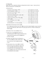
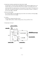
9-3-1. Mounting method of bevel plate (See Figs. 8 and 9.)
(1) Cut out the interlocking caulking portion of
the rivet using an electric drill. On this operation,
never do damage to the base.
Then, remove the rivet to "B" direction from
the base section and remove the Bevel Plate [64]
from the base.
(2) Mount the Bevel Plate [64], the Step Bolt M6 [67],
the Bolt Washer M6 [66] and the Nylon Nut M6 [65]
as shown in Fig. 9. Then, fix the Bevel Plate [64] onto
the base by tightening the Step Bolt M6 [67] and
the Nylon Nut M6 [65] using a wrench.
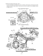
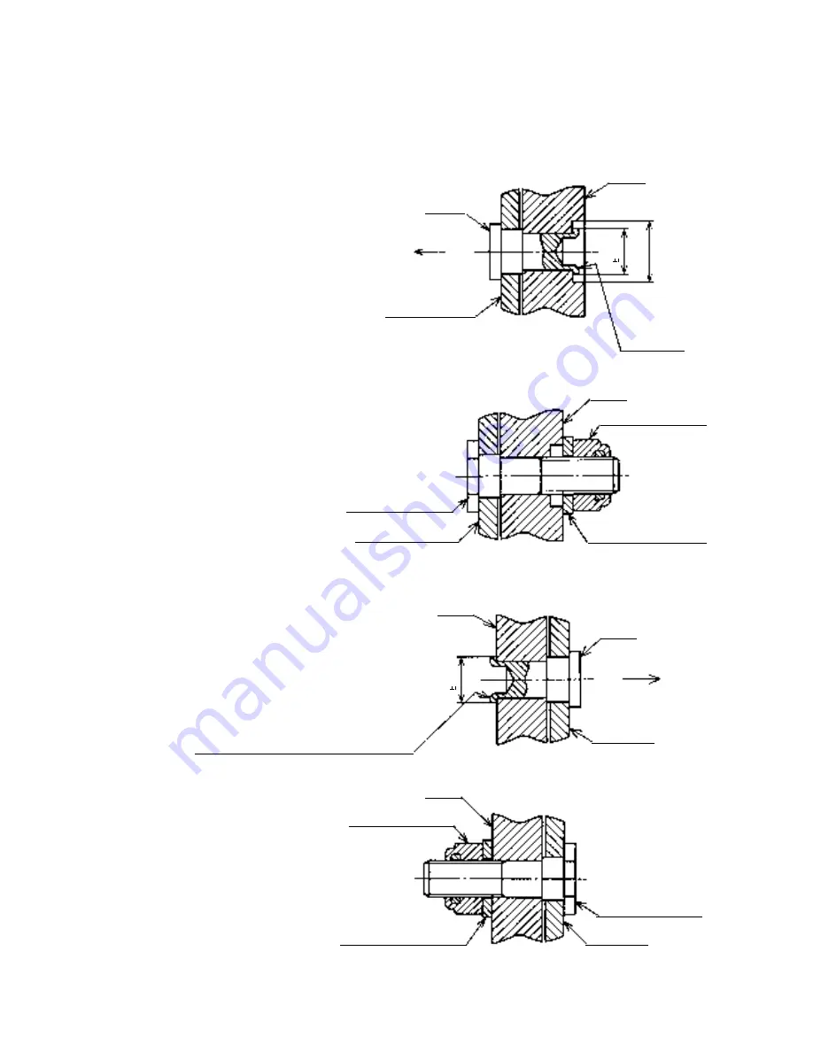
9-3-2. Mounting method of link (See Figs. 10 and 11.)
(1) Cut out the interlocking caulking portion of the rivet
using an electric drill. On this operation, never do
damage to the base. Then, remove the rivet to
"C" direction from the base section and remove
the Link [68] from the base.
(2) Mount the Link [68], the Step Bolt M6 [67],
Bolt Washer M6 [66] and the Nylon Nut M6
[65] as shown in Fig. 11. Then, fix the Link
[68] onto the base by tightening the
Step Bolt M6 [67] and the Nylon Nut M6
[65] using a wrench.
Rivet
B
Interlocking
caulking
portion of
the rivet
10
mm dia.
Base
Base
Bevel Plate [64]
Bevel Plate [64]
Bolt Washer M6 [66]
Fig. 8
Fig. 9
Fig. 10
Fig. 11
7.5
mm dia.
1
7.5
mm dia.
1
Inerlocking caulking portion of the rivet
Base
Rivet
Base
Nylon Nut M6 [65]
Nylon Nut M6 [65]
Link [68]
Link [68]
Step Bolt M6 [67]
Step Bolt M6 [67]
Bolt Washer M6 [66]
C
Summary of Contents for C 7D
Page 25: ......

