--- 16 ---
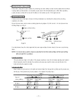
(7) Bevel angle fine adjustment
Grip the handle on the motor head and position it at the bevel angle you need. Temporarily tighten the clamp
lever.
CAUTION: If not tightened firmly enough the motor head might suddenly move or slip, causing
injuries. Be sure to tighten the motor head section enough so it will not move.
Make fine adjustments to the bevel angle by gripping the handle and moving knob (A).
NOTE: Turning knob (A) clockwise, allows fine adjustment of the main unit to the left (as seen from
front).
Turning knob (A) counterclockwise, allows fine adjustment of the main unit to the right (as seen
from front).
If you tilt the main unit in the direction that does not place a load on plate (A) and pull plate (A),
the contact position changes and the right slope angle becomes 3
û
.
If you tilt the main unit in the direction that does not place a load on plate (B) and pull plate (B),
the contact position changes and the right slope angle becomes 48
û
.
After adjusting to the desired angle, tighten the clamp lever and clamp the motor head.
CAUTION: Instruct the customers to always check that the clamp lever is secured and the motor head
is clamped. If customers attempt angle cutting without clamping the motor head, then the
motor head might shift unexpectedly causing injuries.
Fig. 15-1
Fig. 15-2
Handle
8 mm bolt (B)
Knob (A)
Plate (A)
8 mm bolt (A)
Knob (A)
Plate (B)
1
Clamp lever
2
3
Summary of Contents for C12FCH
Page 39: ... 35 Wiring diagram C 12LCH Fig 38 2 ...
Page 40: ... 36 C 12LCH Europe AUS NZL China Fig 39 1 Fig 39 2 ...
Page 41: ... 37 Fig 40 2 Wiring diagram C 12LC USA CAN Fig 40 1 ...
Page 42: ... 38 C 12LC Europe NZL Fig 41 1 Fig 41 2 ...
Page 43: ... 39 Fig 42 2 Wiring diagram C 12FCH USA CAN Fig 42 1 ...
Page 44: ... 40 C 12FCH Europe NZL Asia Fig 43 1 Fig 43 2 ...
Page 76: ... 10 ITEM NO CODE NO DESCRIPTION REMARKS NO USED 6 05 C 12LC Printed in Japan 050630N ...
Page 86: ... 10 ITEM NO CODE NO DESCRIPTION REMARKS NO USED 6 05 C 12FCH Printed in Japan 050630N ...
Page 87: ......


