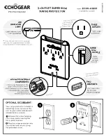
3
4
ED-X31E / ED-X33E (C14B-20)
7. Wiring diagram
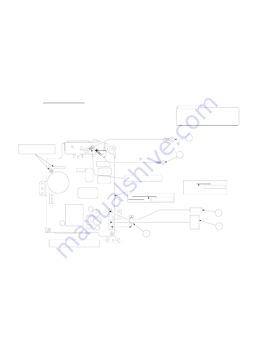
Wiring diagram 1
Wiring of the circuit power unit
(1) Attach the CNGD1 and the CNGD3 with screw.
(2) Connect the TSW after you confirmed the print of the TSW.
(3) Connect the CNPW.
(4) Bundle the CNPW and the TSW with purse lock (PAS1).
Area of Importance
The operations with this symbol have implications
with laws/standards. It is possible to be in violation
of these laws/standards in the case that these operations
are not carried out according to the instructions.
Assemble according to the operation instructions.
TSW
CNPW
PAS1
30±10mm
Touch the CNGD1 to the rotation stop rib,
then attach the CNGD1 with screw.
Make sure to connect the TSW and the CNPW.
You can not confirm the connection at the later process.
Make sure not to touch with adjustment
VR in the power unit board.
Never stress the standing board.
CNGD1
CNGD3
45°
Area of Importance
Area of Importance
Make sure to confirm the print of the TSW.
[YS11A75A-**] (75°C)
Use black silk (printed on board)
circuit power unit.
Circuit power unit


