3
9
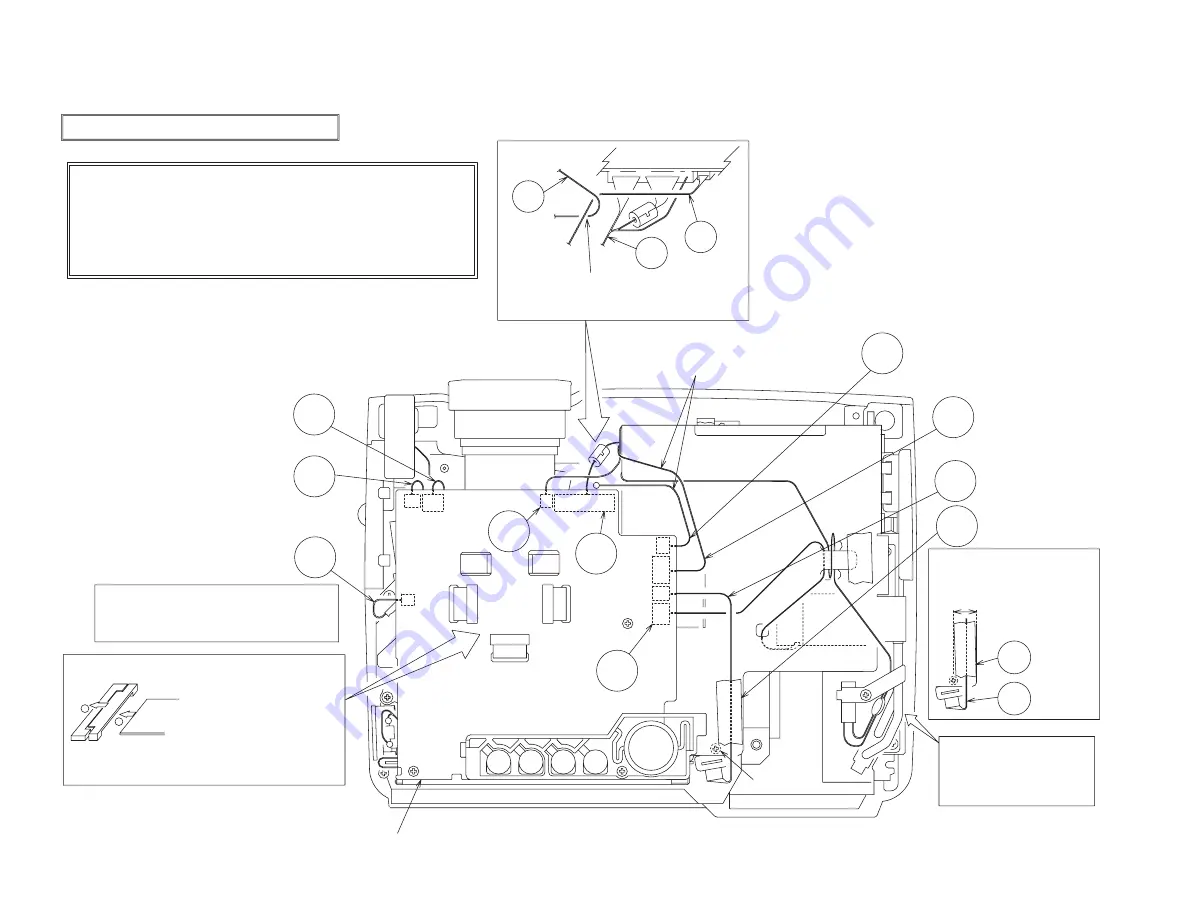
Wiring for Drive Board Installation
Exhaust fan
Fan for panel B
#6220
#3020
#6221
CNRM
E803
E802
E806
X:P601
S:P602
X:P501
S:P502
X:P701
S:P702
E302
E800
E801
E805
E807
E804
CNTH
#6222
CNBAR
CNLC
CNLC
TAP2
TAP2
CNPOW
Fan for panel R
Fan for panel G
(1) Securely insert the flexible
cable into the connector base
(note that the connector is a
bottom contact type so make
sure that the direction in which
you insert it is appropriate).
(2) Move the lock hinge in the
arrowed direction until it is
securely locked.
For details on flexible cable installation, see the
following drawing:
Flexible
cable
Connector
base
Drive board assembly
During drive board installation
(1) Connect the CNTH, the CNPOW, the #6220 and the #6221.
(2) Wire and connect the CNBAR and the #6222.
(3) Connect the CNRM, the CNLC and the #3020.
(4) Apply the TAP2.
(5) Connect the flexible cable for the liquid crystal panel.
(6) Take care not to entangle the lamp leads when installing the upper case.
Procedure
(1) Before installing the drive board, connect the CNBAR and the #6222 while
holding the drive board with your hand.
(2) Put the drive board in the position where you install it then connect the CNTH,
the CNPOW, the #6220 and the #6221 while lifting the rear of the board.
(3) Connect the CNRM, the CNLC, the #3020 and the panel flexible cable.
SW board setscrew
Put the connector CNRM lead into the clearance
between the optical unit and the bottom case
(to prevent the lead from being caught when
installing the upper case).
Lay the CNLC lead so it can be on the
ballast cover and cannot be nearer to
the input board than the SW board
setscrew then tape the lead.
CNLC lead laying range
Install the upper case with care
so the lamp leads cannot be
caught on the case
(pay attention to the rib on the
upper case).
1
2
Pass the #6222 lead over the ballast cover
(if the lead is passed from the side of the
ballast power supply, it will contact the power
supply primary side).
Entwine the CNBAR lead with the CNTH lead
(to prevent them from contacting the primary
side of the power supply).
E800
CNPOW
CNTH
E302
CNBAR
8
9
14
2 1
Summary of Contents for C3S3
Page 34: ...33 Connector connection diagram C3S3E C3XM3E ...
Page 42: ...41 6 5 4 3 2 1 6 5 4 3 2 1 A B C D E F G POWER UNIT BALLAST C3S3 C3XM3 ...
Page 43: ...42 6 5 4 3 2 1 6 5 4 3 2 1 A B C D E F G POWER UNIT CIRCUIT C3S3 C3XM3 ...
Page 44: ...A B C D E F G 5 4 3 2 1 6 6 5 4 3 2 1 PWB assembly DRIVE 1 C3S3 C3XM3 43 1 ...
Page 45: ...A B C D E F G 5 4 3 2 1 6 6 5 4 3 2 1 PWB assembly DRIVE 2 C3S3 C3XM3 44 ...
Page 46: ...A B C D E F G 5 4 3 2 1 6 6 5 4 3 2 1 PWB assembly DRIVE 3 C3S3 C3XM3 45 ...
Page 47: ...A B C D E F G 5 4 3 2 1 6 6 5 4 3 2 1 PWB assembly DRIVE 4 C3S3 C3XM3 46 ...
Page 48: ...A B C D E F G 5 4 3 2 1 6 6 5 4 3 2 1 PWB assembly DRIVE 5 C3S3 C3XM3 47 ...
Page 49: ...A B C D E F G 5 4 3 2 1 6 6 5 4 3 2 1 PWB assembly DRIVE 6 C3S3 C3XM3 48 ...
Page 50: ...A B C D E F G 5 4 3 2 1 6 6 5 4 3 2 1 PWB assembly DRIVE 7 C3S3 C3XM3 49 ...
Page 51: ...A B C D E F G 5 4 3 2 1 6 6 5 4 3 2 1 PWB assembly DRIVE 8 C3S3 C3XM3 50 ...
Page 52: ...A B C D E F G 5 4 3 2 1 6 6 5 4 3 2 1 PWB assembly DRIVE 9 C3S3 C3XM3 51 ...
Page 53: ...A B C D E F G 5 4 3 2 1 6 6 5 4 3 2 1 PWB assembly DRIVE 10 C3S3 C3XM3 52 ...
Page 54: ...A B C D E F G 5 4 3 2 1 6 6 5 4 3 2 1 PWB assembly SIGNAL 1 C3S3 C3XM3 53 ...
Page 55: ...A B C D E F G 5 4 3 2 1 6 6 5 4 3 2 1 PWB assembly SIGNAL 2 C3S3 C3XM3 54 ...
Page 56: ...A B C D E F G 5 4 3 2 1 6 6 5 4 3 2 1 PWB assembly SIGNAL 3 C3S3 C3XM3 55 ...
Page 57: ...A B C D E F G 5 4 3 2 1 6 6 5 4 3 2 1 PWB assembly INPUT 1 C3S3E C3XM3E 56 ...
Page 58: ...A B C D E F G 5 4 3 2 1 6 6 5 4 3 2 1 PWB assembly INPUT 2 C3S3E C3XM3E 57 ...
Page 59: ...A B C D E F G 5 4 3 2 1 6 6 5 4 3 2 1 PWB assembly INPUT 3 C3S3E C3XM3E 58 ...
Page 62: ...THE UPDATED PARTS LIST FOR THIS MODEL IS AVAILABLE ON ESTA ...
Page 64: ...63 ...


