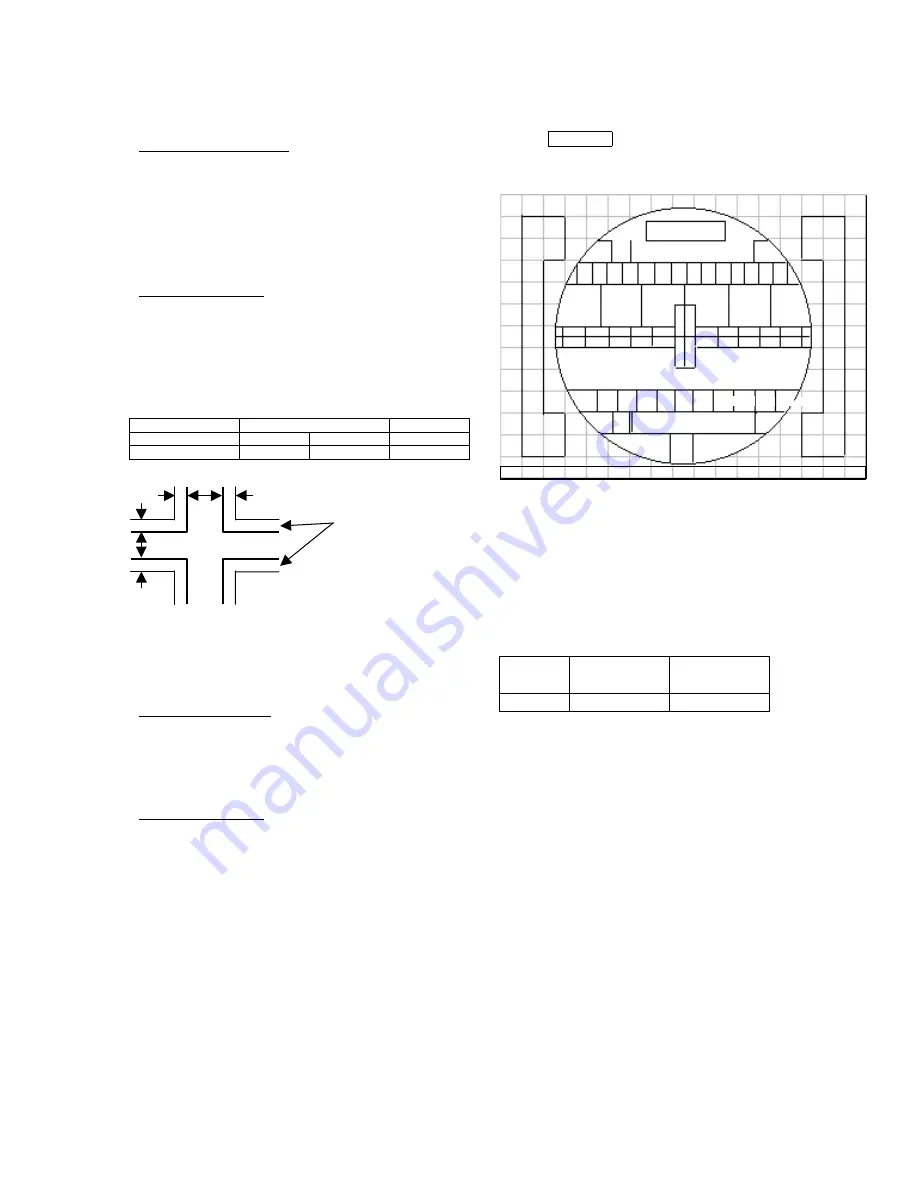
2.15 BLUE DEFOCUS ADJUSTMENT
Preparation for adjustment
(1)
Optical and electrical focus adjustment
should be completed.
(2)
The convergence adjustment should be
completed.
(3)
VIDEO control should be set Factory Preset
condition.
Contrast : Max.
other items : Center
Adjustment procedure
(1)
Input Cross-hatch signal to VIDEO or RF
input.
(2)
Turn the B FOCUS VR fully clockwise.
(3)
Adjust sticking out level of Blue as the spec
of below table with turning the FOCUS VR
counterclockwise.
BLUE DEFOCUS
CHASSIS
DP2M
UNIT
SCREEN SIZE
43”
50”
INCH
STICKKING OUT
1.5~2.0
1.5~2.0
mm
Sticking out
of blue
Note: The view point should be limited to the center
of the screen for this adjustment. (FOB 0.0)
2.16 SUB BRIGHTNESS ADJUSTMENT
Adjustment preparation
(1) Pre-heat 20 minutes or more before the
adjustment.
(2) Receive the color bar signal.
(3) The vertical incident illumination on the screen
should be 20 lux or less.
Adjustment procedure
(1)
Go to “Sub Brightness (item No 38)” adj.
mode by using R/C.
(2)
Adjust Sub brightness as following spec. by
using R/C.
(3) Press “MUTE” key on R/C to write the data.
REMARKS
!
Observe the TV SET screen directly
by eyes; do not use a mirror.
Adjustment specification : Within ±0.3 step
Quality control specification : Within ±0.5 step
* Note: During the SUB-BRIGHTNESS adjustment
mode, TV µcon changes the CONTRAST and the
COLOR controls to Min., but the other controls are
not changed automatically.
Make sure that the other controls are set center.
Sink to
black
Slightly for
black
DP2M
A0
A1
!
Note: Actual procedure;
Once A1 is set to black and is seen
as dark as A0 (the level that the
border of the two cannot be
identified), increase the brightness by
19 steps.
A0
A1 A2
A3
A4 A5
A6
A7 A8
A9
A1
A
Summary of Contents for C43-FD2000
Page 4: ......
Page 5: ......
Page 6: ......
Page 7: ......
Page 8: ......
Page 9: ......
Page 10: ......
Page 11: ......
Page 12: ......
Page 13: ......
Page 22: ......
Page 23: ......
Page 24: ......
Page 25: ......
Page 26: ......
Page 27: ......
Page 28: ......
Page 29: ......
Page 30: ......
Page 31: ......
Page 32: ......
Page 33: ......
Page 34: ......
Page 35: ......
Page 36: ......
Page 37: ......
Page 38: ......
Page 39: ......
Page 40: ......
Page 41: ......
Page 42: ......
Page 43: ......
Page 44: ......
Page 56: ......
Page 57: ......
Page 58: ......
Page 82: ...POWER SUPPLY PWB S902 S903 I901 D901 T901 L902 L901 L905 L911 S901 0 120 325 0 ...
Page 84: ...325 0 325 240 TP01 0 0 FBT I601 REAR VIEW DEFLECTION P W B TH01 REAR VIEW RH17 ...
Page 86: ...SIGNAL SUB P W B Rear view I3A1 I301 I303 I501 I502 ...
Page 89: ......
Page 91: ...C50 FD2000 EXPLODED VIEW ...
Page 92: ......


