69
SERVICE ADJUSTMENTS
2.20.2 CONVERGENCE ERRORS
If there is an error while performing INITIALIZE or MAGIC FOCUS, error code or message appears on the screen
as table below.
When MAGIC FOCUS operates: Error code (GREEN) appears for about 1 second at bottom right corner, and
soon it returns to RF or video signal.
When INITIALIZE operates: Error message (RED) appears all the time.
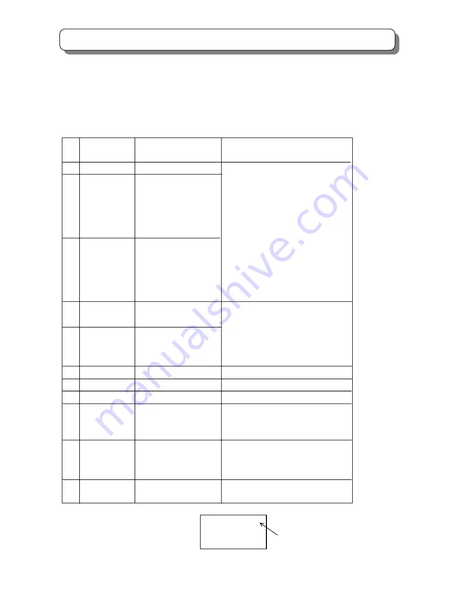
Error Error Contents Countermeasure / Check method
Code Massage
1 VF ERROR ! EEPROM Write Error Replace the DCU
2 CONNECT1 ! Connection Check Error Darken outside light
No.01234567 (Pattern is not detected) Check the placement of the sensor
OVER FLOW ! Is pattern hitting to sensor?
No.01234567 Check connection and solder bridge of
*1 sensor
3 A/D LEVEL ! Calibration Error Replace the sensor
No.01234567 (Small difference between Check Sensor connector
OVER FLOW ! High and Low brightness) Check Sensor PWB
No.01234567 Adjustment check
*1 (H/V size, centering)
4 OVER FLOW ! Data Over Flow Error Check the placement of the sensor
(Saturation of corr. Data) Adjustment check
5 CONVERGENCE! Convergence Error (H/V size, centering)
(The number of ADJ. Times Conv. AMP circuit check
is more than setting.)
6 LOOP COUNT ! Not Used
7 OPERATION ! Make Setup Data Error Same as error code 4
8 CHECK SUM ! Different SRAM-EEPROM Replace the DCU
9 CONNECT2 ! Connect Data Set Error Same as error code 2
No.01234567 (ADJ. Parameter PORT80-87
*1 is wrong setting)
10 NOISE ! Sensor Noise Error Input strong field strength signal.
Check the wiring dress of connector
between sensor and DCU.
11 SYNC ! H BLK, V BLK Error Input strong field strength signal.
Input standard signal NTSC or PAL.
REMARKS *1) Relation of sensor No. and screen position as shown below.
On screen
(View from front side) sensor No. 0-7
6 5 4
0 1 2
7 3
Summary of Contents for C43-FD7000
Page 72: ...72 SERVICE ADJUSTMENTS SIGNAL SUB P W B IG02 IG03 IG04 IQ01 IQ02 IR01 Rear view IG01 I R 0 2 ...
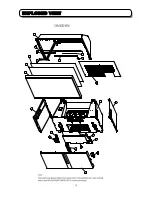
Page 78: ...78 EXPLODED VIEW ...
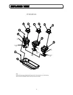
Page 79: ...79 EXPLODED VIEW ...
Page 143: ......
Page 144: ......
Page 145: ......
Page 146: ......
Page 147: ......
Page 150: ......
Page 151: ......
Page 152: ......
Page 153: ......
Page 154: ......
Page 155: ......
Page 156: ......
Page 157: ......
Page 158: ......
Page 159: ......
Page 160: ......
Page 161: ......
Page 162: ......
Page 163: ......
Page 164: ......
Page 165: ......
Page 166: ......
Page 167: ......
Page 168: ......
Page 169: ......
Page 170: ...SIGNAL SIDE A P W B ...
Page 171: ...SIGNAL SIDE B P W B ...
Page 172: ...SIGNAL SUB SIDE A P W B ...
Page 173: ...SIGNAL SUB SIDE B P W B ...
Page 174: ...TUNER SIDE A P W B ...
Page 175: ...TUNER SIDE B P W B ...
Page 176: ...AUTO POWER AV INPUT CONVER SENSOR SW P W B ...
Page 177: ...CPT CONTROL AV NET LED P W B ...
Page 178: ...POWDEF P W B ...
Page 179: ......


