13
.
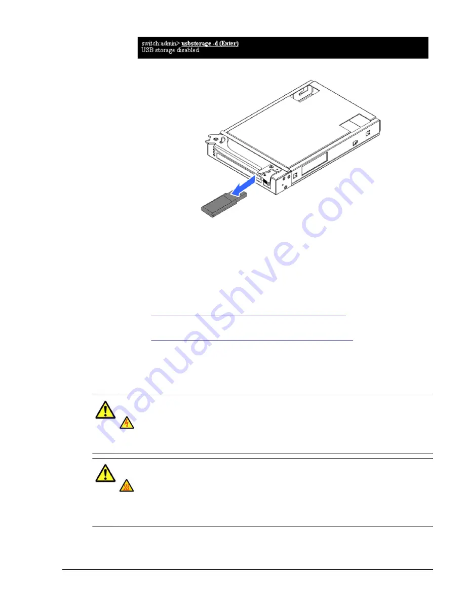
Remove the USB memory.
Figure 5-152 Removing a USB memory
Installing a USB memory
1
.
Put on an anti-static wrist strap.
2
.
Reverse the removal procedure.
3
.
Turn off LID LED for identifying the target module.
See
Identify LED (LID) on/off procedure on page 4-7
4
.
Turn off the maintenance mode from web console.
See
Maintenance mode on/off procedure on page 4-10
section.
Replacing a power supply module
This procedure describes how to replace a power supply.
WARNING:
To prevent the risk of electrical shock, disconnect power cord before
removing power supply module.
CAUTION:
High temperature component.
Do not touch the power supply module after removing the power cord.
Wait 5 or more minutes before holding the power supply module to
reduce the risk of serious burn injuries from hot surfaces.
Replacing parts
5-121
Hitachi Compute Blade 500 Series System Service Manual
Summary of Contents for CB 520A A1
Page 26: ...xxvi Preface Hitachi Compute Blade 500 Series System Service Manual ...
Page 152: ...4 64 Common process for replacement Hitachi Compute Blade 500 Series System Service Manual ...
Page 294: ...6 12 Identifying RAID rebuild status Hitachi Compute Blade 500 Series System Service Manual ...
Page 432: ...9 16 Updating firmware Hitachi Compute Blade 500 Series System Service Manual ...
Page 439: ...Change LOM configuration 10 7 Hitachi Compute Blade 500 Series System Service Manual ...
Page 442: ...10 10 Change LOM configuration Hitachi Compute Blade 500 Series System Service Manual ...
Page 450: ...10 18 Change LOM configuration Hitachi Compute Blade 500 Series System Service Manual ...
Page 464: ...11 14 Troubleshooting Hitachi Compute Blade 500 Series System Service Manual ...
Page 465: ...Hitachi Compute Blade 500 Series System Service Manual ...


