Symbol
Component
1
Management module #1
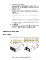
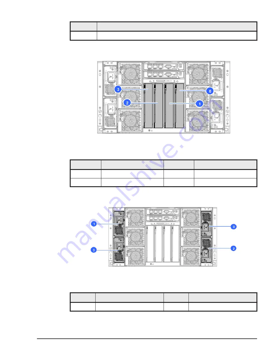
Switch module numbering
Figure 1-8 Location in server chassis
Table 1-4 Location of installable components
Symbol
Component
Symbol
Component
0
Switch module #0
2
Switch module #2
1
Switch module #1
3
Switch module #3
Power supply module numbering
Figure 1-9 Location in server chassis
Table 1-5 Location of installable components
Symbol
Component
Symbol
Component
0
Power supply module #0
2
Power supply module #2
Introduction
1-7
Hitachi Compute Blade 500 Series System Service Manual
Summary of Contents for CB 520A A1
Page 26: ...xxvi Preface Hitachi Compute Blade 500 Series System Service Manual ...
Page 152: ...4 64 Common process for replacement Hitachi Compute Blade 500 Series System Service Manual ...
Page 294: ...6 12 Identifying RAID rebuild status Hitachi Compute Blade 500 Series System Service Manual ...
Page 432: ...9 16 Updating firmware Hitachi Compute Blade 500 Series System Service Manual ...
Page 439: ...Change LOM configuration 10 7 Hitachi Compute Blade 500 Series System Service Manual ...
Page 442: ...10 10 Change LOM configuration Hitachi Compute Blade 500 Series System Service Manual ...
Page 450: ...10 18 Change LOM configuration Hitachi Compute Blade 500 Series System Service Manual ...
Page 464: ...11 14 Troubleshooting Hitachi Compute Blade 500 Series System Service Manual ...
Page 465: ...Hitachi Compute Blade 500 Series System Service Manual ...

