background image

8

  For outstanding performance and reliability, always use Hitachi 

nylon cutting line. Never use wire or other materials that could 

become a dangerous projectile.

  If the cutting head does not feed cutting line properly, check 

that the nylon line and all components are properly installed. 

Contact your Hitachi dealer if you need assistance.

3. Installation 

(

Fig.


14

)

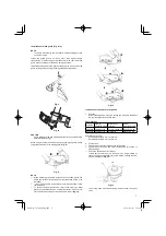
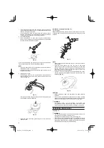
  Install cutting head on gear case of grass trimmers/brush 

cutters. The mounting nut is left-hand-threaded. Turn clockwise 

to loosen/counterclockwise to tighten. 

19

Fig.


14

For curved shaft models, the mounting nut is right-hand-threaded. 

Turn counterclockwise to loosen/clockwise to tighten. 

NOTE

  Since the cutter holder cap is not used here, keep it for when a 

metal blade is used, if so equipped. 

  Insert Allen wrench (19) into the hole of the gear case in order to 

lock the cutter holder.

4.  Adjusting line length

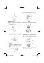
  Set the engine speed as low as possible and tap the head on 

the ground. The nylon line will be drawn out about 3 cm with 

each tap. (

Fig.


15

)

Fig.


15


Also, you can extend the nylon line by hand but the engine must 

be completely stopped. (

Fig.


16

Fig.


16

  Adjust the nylon line to the proper length of 11–14 cm before 

each operation.

Installation


of


cutting


blade

 (

Fig.


17

)

(If so equipped)

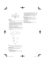
When installing a cutting blade, make sure that there are no cracks 

or any damage in it and that the cutting edges are facing the correct 

direction.

21

20

22

23

19

Fig.


17

NOTE

  When installing cutter holder cap (20), be sure to set concave 

side upward.

  Insert the alien wrench (19) into the hole of the angle 

transmission in order to lock the cutter holder (21). Please note 

that the cutter 

fi

 xing bolt or nut (22) has left-handed threads, 

(clockwise to loosen/ counter-clockwise to tighten). Tighten the 

fi

 xing bolt or nut with the box wrench.

  If your unit is of a nut securing type and equipped with a cotter 

pin, the blade must be retained with a new pin (23) each time 

installed. (

Fig.


18

)

23

Fig.


18

CAUTION

  Before operation, make sure the blade has been properly 

installed.

  If your unit is equipped with protection cover under a cutting 

blade, check it for wear or cracks before operation. If any damage 

or wear is found, replace it, as it is an article of consumption.


WARNING

  For Hitachi heads, use only 

fl


exible, non-metallic line 

recommended by the manufacturer. Never use wire or wire 

ropes. They can break o

  and become a dangerous projectile.

OPERATING


PROCEDURES

Fuel

 (

Fig.


19

)


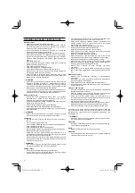
WARNING

  The trimmer is equipped with a two-stroke engine. Always run 

the engine on fuel, which is mixed with oil.


Provide good ventilation, when fueling or handling fuel.

  Fuel contains highly 

fl

 ammable and it is possible to get the 

serious personal injury when inhaling or spilling on your body. 

Always pay attention when handling fuel. Always have good 

ventilation when handling fuel inside building.

000Book̲CG22EAS̲Eng.indb   8

000Book̲CG22EAS̲Eng.indb   8

2010/01/18   17:16:09

2010/01/18   17:16:09

Summary of Contents for CG 22EAB(L)

Page 1: ...efore using this machine carefully read through these HANDLING INSTRUCTIONS to ensure efficient safe operation It is recommended that these INSTRUCTIONS be kept readily available as an important reference when using this machine 000Book CG22EAS Eng indb 1 000Book CG22EAS Eng indb 1 2010 01 18 17 16 08 2010 01 18 17 16 08 ...

Page 2: ...ical area A dangerous reaction may occur causing the entire unit and operator to be thrust violently This reaction is called blade thrust As a result the operator may lose control of the unit which may cause serious or fatal injury Blade thrust is more likely to occur in areas where it is difficult to see the material to be cut Keep all children bystanders and helpers 15 m away from the unit If anyo...

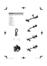
Page 3: ...utting attachment 6 Drive shaft tube 7 Handle 8 Suspension eyelet 9 Ignition switch 10 Harness 11 Throttle trigger lockout 12 Choke lever 13 Engine 14 Angle transmission 15 Joint case 16 Combi box spanner 17 Handling instructions 16 17 10 13 11 9 7 6 14 5 4 2 13 11 9 7 15 6 14 5 4 2 13 9 11 7 6 5 4 2 2 9 11 13 8 7 6 5 14 4 3 12 1 000Book CG22EAS Eng indb 3 000Book CG22EAS Eng indb 3 2010 01 18 17 ...

Page 4: ...itches furnaces etc WARNING Fuel is easy to ignite or get explosion or inhale fumes so that pay special attention when handling or filling fuel Cutting safety Do not cut any material other than grass and brush Inspect the area to be cut before each use Remove objects which can be thrown or become entangled For respiratory protection wear an aerosol protection mask when cutting the grass after inse...

Page 5: ... 1 7 7 4 7 4 1 3 7 10 1 5 5 5 5 6 6 5 5 4 7 5 5 8 1 NOTE Equivalent noise level vibration level are calculated as the time weighted energy total for noise vibration levels under various working conditions with the following time distribution 1 2 Idle 1 2 racing All data subject to change without notice ASSEMBLY PROCEDURES Drive shaft to engine Fig 1 Loosen tube locking bolt 1 about ten turns so th...

Page 6: ...r unit has handle location label on drive shaft tube follow the illustration Remove the handle bracket 7 from the assembly Fig 4 Place the handles and attach the handle bracket with four bolts lightly Adjust to appropriate position Then attach it firmly with the bolts 7 Fig 4 Attach the protection tube to the drive shaft or handle using cord clamps 8 Fig 5 8 Fig 5 Throttle wire stop cord Press the...

Page 7: ...d extension refer to the drawings Wear gloves as the extension has a sharp line limiter then push the four square tabs on the guard one by one in order Fig 12 Fig 12 Installation of semi auto cutting head 1 Function Automatically feeds more nylon cutting line when it is tapped at low rpm not greater than 4500 rpm Specifications Code No Type of attaching screw Direction of rotation Size of attachin...

Page 8: ...ting edges are facing the correct direction 21 20 22 23 19 Fig 17 NOTE When installing cutter holder cap 20 be sure to set concave side upward Insert the alien wrench 19 into the hole of the angle transmission in order to lock the cutter holder 21 Please note that the cutter fixing bolt or nut 22 has left handed threads clockwise to loosen counter clockwise to tighten Tighten the fixing bolt or nu...

Page 9: ...en filling up with fuel so that possible over pressure disappears Tighten the fuel cap carefully after fueling Always move the trimmer at least 3 m from the fueling area before starting Always wash any spilled fuel from clothing immediately with soap Be sure to check for any fuel leakage after refueling Before fueling clean the tank cap area carefully to ensure that no dirt falls into the tank Mak...

Page 10: ...ne and make sure that the attachment and related parts are undamaged When grass or vines wrap around attachment stop engine and attachment and remove them Stopping Fig 28 29 Decrease engine speed and run at an idle for a few minutes then turn off ignition switch 24 For models with an engine ignition switch keep the ignition switch pressed until the engine comes to a complete stop 26 24 Fig 28 24 Fi...

Page 11: ...d completely Therefore it must regularly be replaced with a new one A damaged filter must always be replaced Fuel filter Fig 32 Drain all fuel from fuel tank and pull fuel filter line from tank Pull filter element out of holder assembly and rinse element in warm water with detergent Rinse thoroughly until all traces of detergent are eliminated Squeeze do not wring away excess water and allow eleme...

Page 12: ... on the center partition of the reel Wind both halves of the line on the reel in the same direction keeping each half of the line on its own side of the partition Fig 37 32 10 cm Fig 37 4 Push each line into the stopper holes 33 leaving the loose ends approx 10 cm in length Fig 38 10 cm 33 1 0 c m Fig 38 5 Insert both loose ends of the line through the cord guide 34 when placing the reel in the ca...

Page 13: ...l find some general maintenance instructions For further information please contact your Hitachi dealer Daily maintenance Clean the exterior of the unit Check that the harness is undamaged Check the blade guard for damage or cracks Change the guard in case of impacts or cracks Check that the cutting attachment is properly centred sharp and without cracks An off centre cutting attachment induces hea...

Page 14: ...14 CG22EAS 000Book CG22EAS Eng indb 14 000Book CG22EAS Eng indb 14 2010 01 18 17 16 09 2010 01 18 17 16 09 ...

Page 15: ...15 CG22EAS CG22EAD 000Book CG22EAS Eng indb 15 000Book CG22EAS Eng indb 15 2010 01 18 17 16 10 2010 01 18 17 16 10 ...

Page 16: ...16 CG22EAD 000Book CG22EAS Eng indb 16 000Book CG22EAS Eng indb 16 2010 01 18 17 16 11 2010 01 18 17 16 11 ...

Page 17: ...17 CG22EAB 000Book CG22EAS Eng indb 17 000Book CG22EAS Eng indb 17 2010 01 18 17 16 12 2010 01 18 17 16 12 ...

Page 18: ...18 CG22EAB 000Book CG22EAS Eng indb 18 000Book CG22EAS Eng indb 18 2010 01 18 17 16 13 2010 01 18 17 16 13 ...

Page 19: ...19 000Book CG22EAS Eng indb 19 000Book CG22EAS Eng indb 19 2010 01 18 17 16 14 2010 01 18 17 16 14 ...

Page 20: ...E99005311 G Printed in China Shinagawa Intercity Tower A 15 1 Konan 2 chome Minato ku Tokyo Japan Hitachi Koki Co Ltd 000Book CG22EAS Eng indb 20 000Book CG22EAS Eng indb 20 2010 01 18 17 16 14 2010 01 18 17 16 14 ...

Reviews: