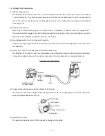
--- 8 ---
9. PRECAUTIONS IN DISASSEMBLY AND REASSEMBLY
The
[Bold]
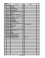
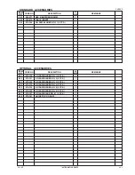
numbers in the descriptions below correspond to the part numbers in the Model CJ 65V3 Parts List.
The disassembly and reassembly procedures are the same for the Model CJ 65S3, with the exception of the
switch and the wiring diagrams. Where the part numbers are different, those in parentheses are for the Model
CJ 65S3.
9-1. Disassembly
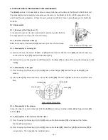
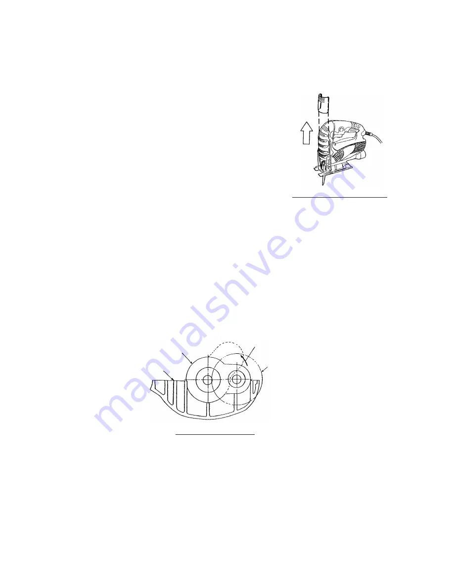
9-1-1. Removal of the Chip Cover [1]
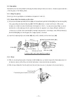
In the same manner as it is slid up and down for positioning, slide the Chip
Cover
[1]
upward to remove it from the main body.
9-1-2. Removal of the Guard Bar [2]
Stretch both ends of the Guard Bar
[2]
and remove it from the main body.
9-1-5. Disassembly of the plunger
Loosen the Seal Lock Hex. Socket Hd. Bolt M3 x 8
[25]
and remove the Blade Holder
[22]
, Plunger Holder
[21]
and Felt
[24]
.
9-1-6. Disassembly of the armature and the stator
(1) From housing (A) of Housing (A).(B) Set
[4]
, remove the Brush Holders
[15]
, and take out the Carbon
Brushes
[14]
(two pieces).
(2) From housing (A) of Housing (A).(B) Set
[4]
, remove the Holder
[29]
, Stator Ass'y
[33]
and Armature
[31]
in
a single body. Then separate the individual parts.
9-1-3. Disassembly of Housing (B)
(1) Remove the Hex. Socket Hd. Bolt M4 x 16
[19]
with the Hex. Bar Wrench 3 mm
[501]
(standard accessory),
and remove the Base
[11]
and the Roller Holder
[17]
.
(2) Remove the seven Tapping Screws (W/Flange) D4 x 20 (Black)
[7]
, and take off housing (B) of Housing (A).(B)
Set
[4]
.
9-1-4. Disassembly of the gear
(1) From housing (A) of Housing (A).(B) Set
[4]
, take out the Plunger
[23]
and the Plunger Holder
[21]
(two
pieces).
(2) Lift the Gear
[27]
upward and remove it from the Holder
[29]
. Washer (C)
[28]
can be removed at the same
time.
How to remove the chip cover
Holder
[29]
Gear removal procedure
Lift upward.
Gear
[27]
Housing (A)

